Method for encoding/decoding error correcting code, transmitting apparatus and network

a technology of error correction and error correction code, applied in the field of encoding/decoding an error correction code, a transmitting apparatus and a network, can solve the problems of degrading signal quality, eight-error correction reed-solomon code alone is not sufficient to realize such a compensation, and achieve the effect of maximizing the transmission distan

Inactive Publication Date: 2006-04-04
HITACHI LTD
View PDF6 Cites 45 Cited by
  • Summary
  • Abstract
  • Description
  • Claims
  • Application Information

AI Technical Summary

Benefits of technology

[0012]It is an object of the present invention to provide a method for encoding / decoding an error correcting code suitable for maintaining an original transmission distance when the degree of time division multiplexing for an optical signal is increased, for maximizing a transmission distance for a mixture of optical signals at different bit rates under the wavelength division multiplexing, and for increasing a regenerator interval on condition that the degree of time division multiplexing is not changed, a transmitting apparatus using the method, and a network.

Problems solved by technology

However, since a higher degree of time division multiplexing causes a reduced bit width of signals and a degradation in the signal quality resulting from the influence of a variety of dispersion or nonlinearity, which are physical properties inherent to the optical fibers, a certain signal quality can be maintained only over a shorter transmission distance.
Since the gain of the eight-error-correcting Reed-Solomon code is 5.4 dB for a bit error ratio of 10−12 in consideration of an increase in the transmission rate by approximately 7%, this error correcting code alone is not sufficient to realize the above-mentioned double increase of the transmission capacity.
However, the eight-error-correcting Reed-Solomon code alone is not sufficient to realize such a compensation.
For example, when the regenerator interval is increased four times, a compensation for a loss of 6 dB or more is required, in which case the eight-error-correcting Reed-Solomon code alone is not sufficient to realize such a compensation.
For this reason, when a client signal is STM-64 or the like, a codec unit including an encoder and a decoder will be increased in size, resulting in a higher price of a device which contains the codec unit.

Method used


Image

  • Method for encoding/decoding error correcting code, transmitting apparatus and network
  • Method for encoding/decoding error correcting code, transmitting apparatus and network
  • Method for encoding/decoding error correcting code, transmitting apparatus and network

Examples


first embodiment

(First Embodiment)

[0046]A method of encoding an error correcting code according to one embodiment of the present invention will be described below with reference to FIGS. 1, 2, 20 and 21.

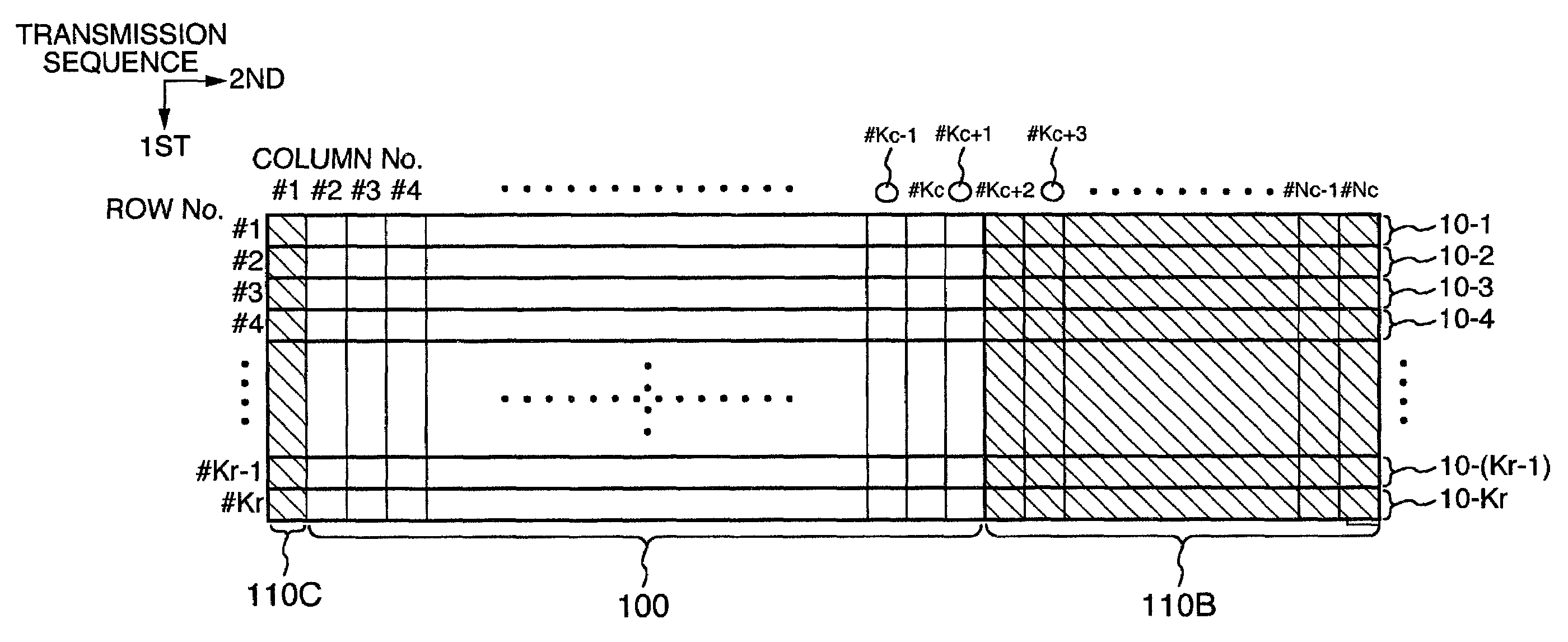
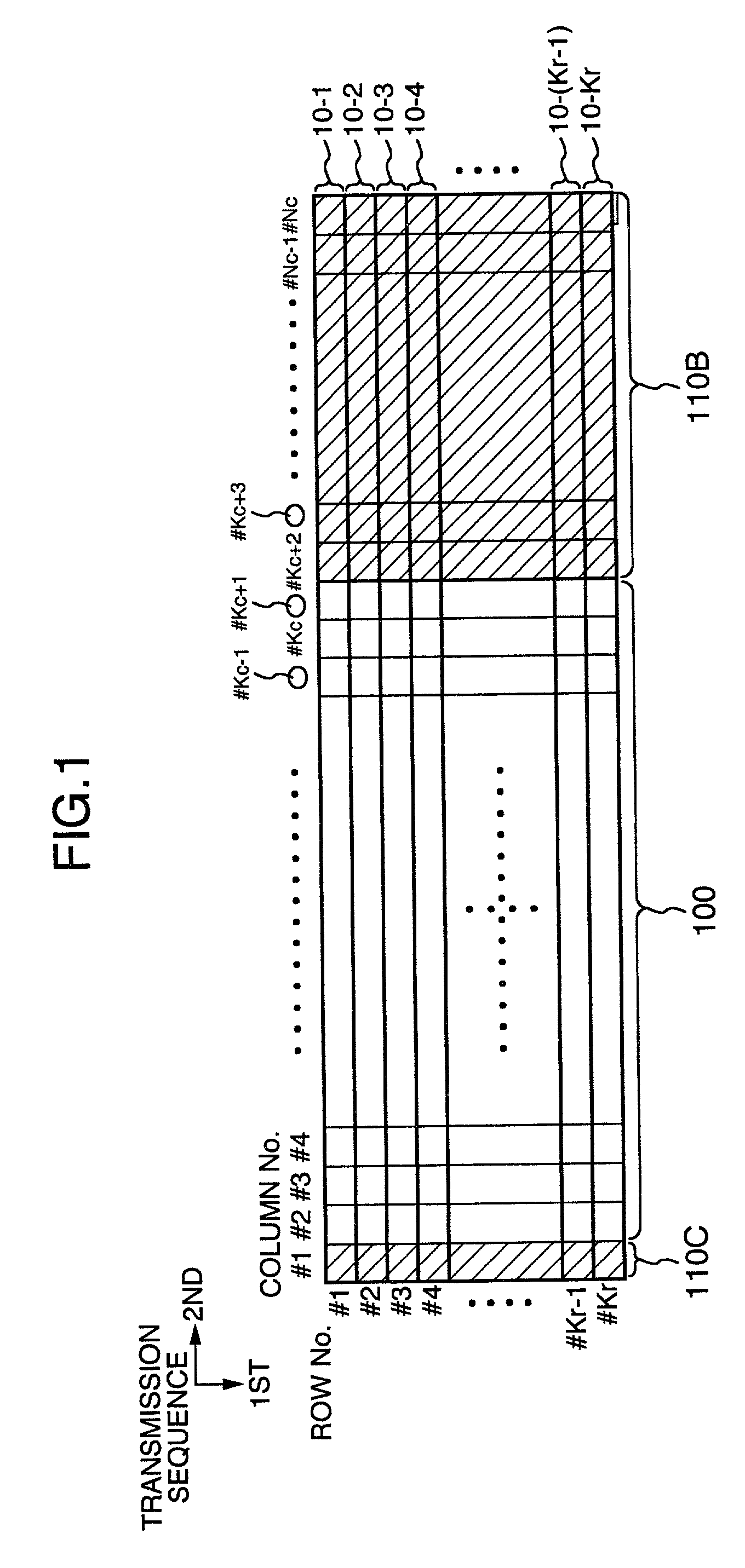
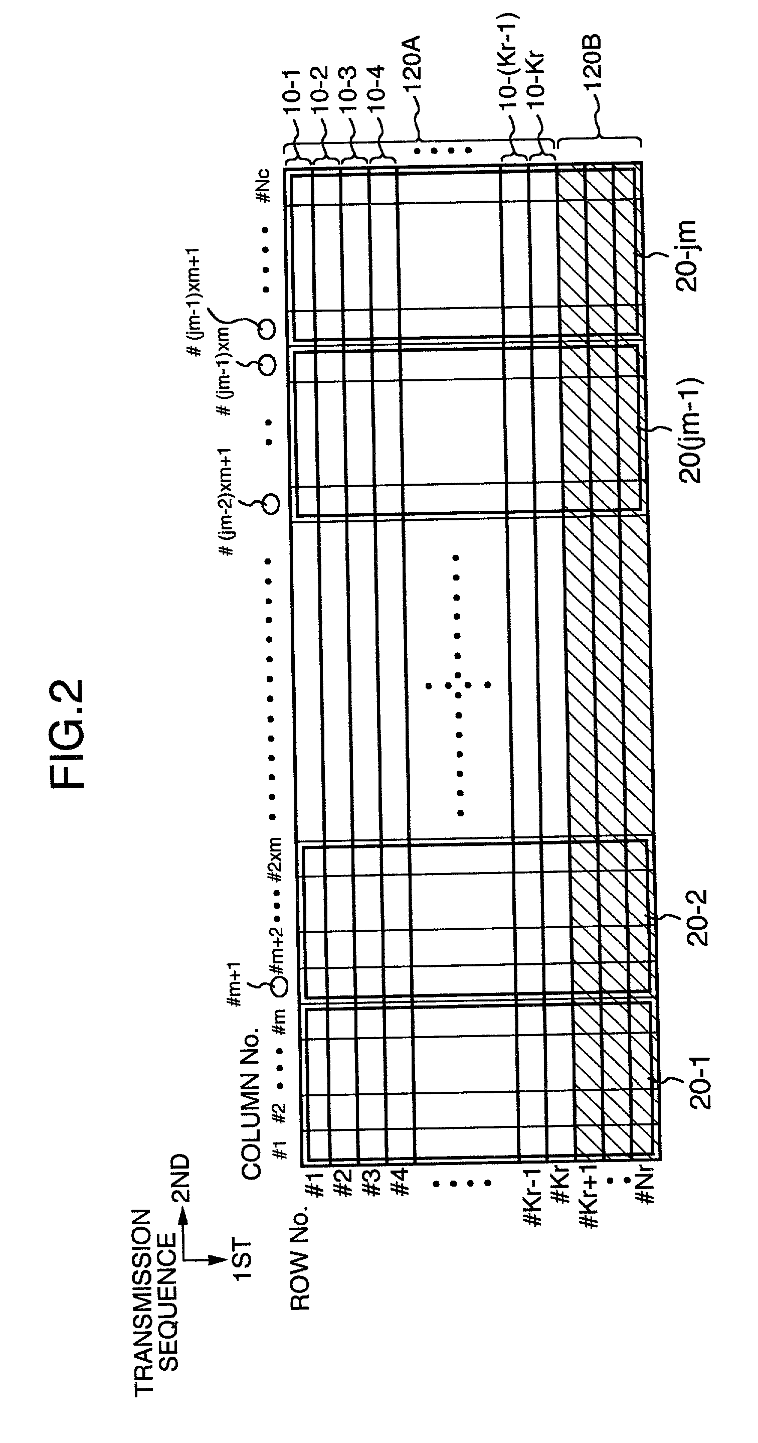
[0047]FIGS. 1 and 2 show an information data area and an encoded area in a frame structure.

(Description of Encoding Side)

[0048]The following description is directed to an encoding side which receives a client signal from a transmission path on a client side, error-correction-encodes the client signal, and then transmits the resulting signal to a super line side as a super FEC signal.

[0049]While the client signal may be either an electric signal or an optical signal in practice, it is assumed herein that, when an optical signal is concerned, the optical signal converted to an electric signal is the client signal.

[0050]A client signal having serial bits arranged on a time series basis is segmented into blocks of (Kr×Kc) bytes (called the “first coded information block”), and each of the first coded in...

second embodiment

(Second Embodiment)

[0105]A second embodiment of the method for encoding an error correcting code according to the present invention is shown in FIGS. 3 and 4. Here, FIGS. 3 and 4 each show an area for coded data in a frame structure.

[0106]The embodiment shown in FIGS. 3, 4, which are similar to the embodiment shown in FIGS. 1, 2, respectively, is a particular case where Kc=238, Nc=255, Kr=16, and Nr=18.

[0107]Also, with δ=1, a client signal is parallellized to 16 bytes on a byte-by-byte basis. Each of the parallellized 16 bytes corresponds to 16 rows. Also, each byte is parallellized on a bit-by-bit basis, so that the client signal is parallellized to 128 row in consequence.

[0108]When code subblocks 10-i for the C1-encoding comprise 16 subblocks each having a length of 255 bytes corresponding to each of 16 rows, either of the following two can be employed as the C1 code:[0109]an eight-error-correcting RS code (255, 239); and[0110]an eleven-error-correcting shortened BCH code (2040, 1...

third embodiment

(Third Embodiment)

[0125]Another embodiment of the method for encoding an error correcting code according to the present invention is shown in FIGS. 5 and 6. Here, FIGS. 5 and 6 each show an area for coded data in a frame structure.

[0126]The embodiment shown in FIGS. 5, 6, which are similar to the embodiment shown in FIGS. 1, 2, respectively, is a particular case where Kc=232, Nc=256, Kr=56, and Nr=64.

[0127]Also, in a manner similar to the second embodiment, with δ=1, a client signal is parallellized to 56 bytes on a byte-by-byte basis. Each of the parallellized 56 bytes corresponds to 56 rows. Also, each byte is parallellized on a bit-by-bit basis, so that the client signal is parallellized to 448 bits as a consequence.

[0128]When code subblocks 10-i for C1-encoding comprise 56 subblocks each having a length of 256 bytes corresponding to each of 56 rows, either of the following two may be employed as the C1 code:[0129]an eleven-error-correcting RS code (255, 233) which has the last o...


PUM


Abstract

A client signal having a constant bit rate is segmented every a bytes to create code information blocks. The bit rate of the client signal is increased such that the client signal has the code information block and an empty area comprised of b bytes, and the ratio c/a is equal to or higher than 110% to create a code block 3 comprised of c bytes. The code information block in the code block is encoded such that an error correcting code is included therein to have an encoding gain of 6 dB or higher for a bit error ratio of 10−12. Associated check bits are placed in the empty area to eventually generate a super FEC signal.

Description

BACKGROUND OF THE INVENTION[0001]The present invention relates to a method for encoding / decoding an error correcting code, a transmitting apparatus and a network which are suitable for use in optical communication networks.[0002]At present, with the advance of digital signal processing technologies based on LSIs and so on, encoding / decoding technologies for error correcting codes have been used in a wide variety of applications for purposes of ensuring a high signal quality. Particularly, among block codes which have a mathematically well-defined organization, a code called “systematic code” is usually used for engineering purposes due to its transparency to information. The systematic code involves segmenting a series of continuous signals into consistent blocks and encoding each of the segmented blocks, and features that only a check bit is added to an empty region, which has been previously determined within the signals, without manipulating information in the original signals. T...

Claims


Application Information

Patent Timeline
Patent Type & Authority Patents(United States)
IPC IPC(8): H03M13/03G06F11/10H03M7/14H03M13/15H03M13/27H03M13/29H04L1/00
CPCH04L1/0083
Inventor OHIRA, MASAKITAKATORI, MASAHIROMORI, TAKASHI
Owner HITACHI LTD
Why Eureka
Try Eureka