This helps you quickly interpret patents by identifying the three key elements:
Problems solved by technology
Method used
Benefits of technology
Benefits of technology
[0021]The technique of simultaneous suppression of PDG and PMD proposed herein is much cheaper than multiplexing orthogonally polarized pumps and more effective than the other approaches.
[0022]The major value of the invention is that with the help of the application of a widebandfiber Raman amplifier with tailored polarization properties it is possible to meet requirements of increased optical fiber capacity at reduced operating and maintaining cost through optimization of three factors:
[0025]Thirdly, with the help of a distributed FRA it is possible to increase bit rate above 40 Gb / s through minimization of the transmission impairments caused by polarization mode dispersion and polarization dependent gain of FRA. Finally, the application of FRA will maximize the transmission distance over 1500 km.
Problems solved by technology
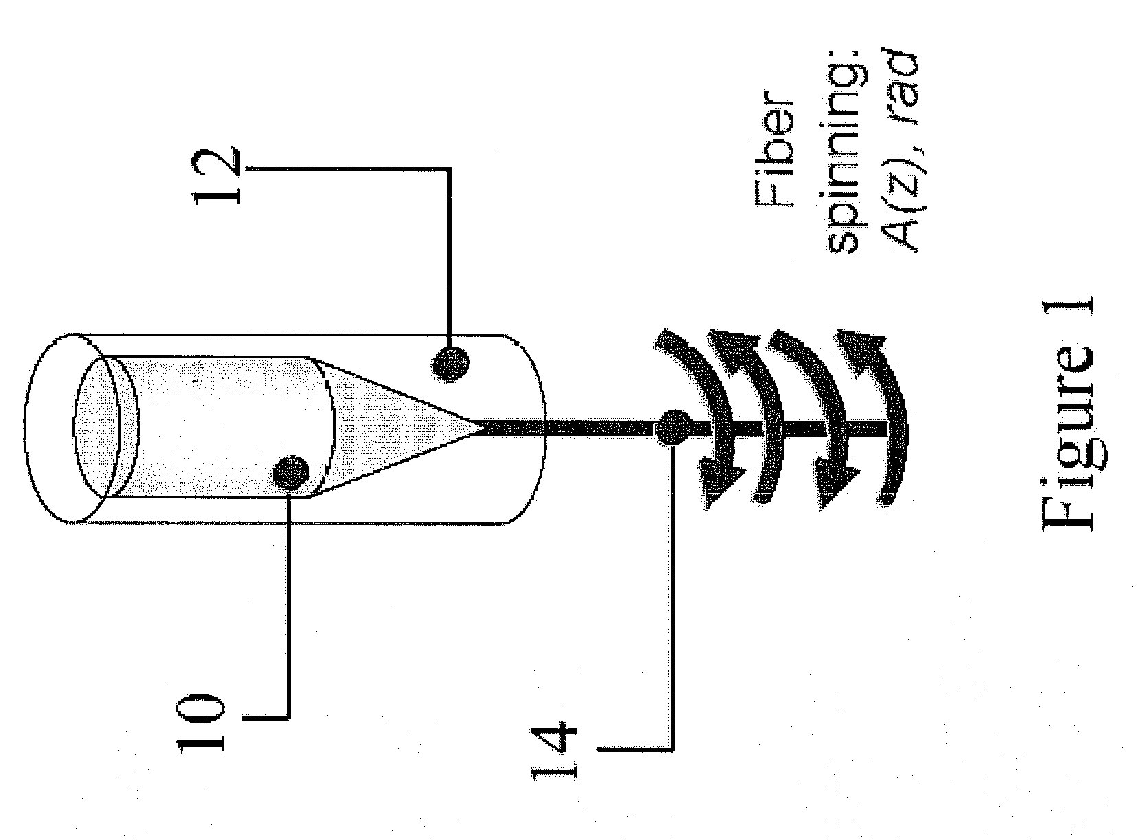
More particularly, a torque is applied to the fiber as it is drawn such that the fiber is caused to twist around its longitudinal axis with a resulting torsional deformation of the fiber material.
Most of the existing schemes to mitigate the PDG are rather expensive, for example, polarization multiplexing of pump laser diodes or application of depolarizers, or not effective, for example, backward pumping or linear-circular conversion of the pump polarization in the case of low PMD fibers.
Because this leads to a decrease not only in PDG, but also in the average gain, this method is not fully effective.
Besides, as follows from E. Bettini, A. Galtarossa, L. Palmieri, M. Santagiustina, L. Schenato, and L. Ursini, “Polarized Backward Raman Amplification in Unidirectionally Spun Fibers,” IEEE Photon. Tech. Lett. 20, 27-29 (2008) (incorporated herein by reference in its entirety), PDG for a lumped FRA based on unidirectionally spun fiber can exceed 20 dB for the backward pump, which makes this technique not effective.
As follows from FIG. 3, minimum and maximum PDGs converge at low PMD values and, therefore, application of linear-to-circular SOP conversion is not effective for FRA at low PMD.
However, temperature fluctuations cause fluctuations in the input SOP around linearly polarized states.
Method used
Image
Click on the blue label to locate the original text in one second.
Reading with bidirectional positioning of images and text.
Examples
first embodiment
[0037]In order to suppress both PDG and PMD, in a first embodiment a short length (L1=zn) of unspun optical fiber is contiguous with a much longer length of periodically spun fiber. For this embodiment, projections max> and min> are the same at the input of the length of periodically spun fiber and, therefore, do not contribute to the PDG over the length of this fiber for a wide range of spinning amplitudes—FIGS. 4(b) and 5(a). It means that for a two-section fiber, polarization dependent gain is the same as for a single section fiber without spin, i.e. it can be very small, FIG. 5.
[0038]Therefore for this case, the differential group delay (DGD):
√{square root over (Δτ(L)2)}=Dp√{square root over (L)}
where L is the fiber length and Dp is the polarization mode dispersion parameter (PMD), for a long-length periodically spun fiber is much less than DGD for a short section of fiber without spin. Thus, the SIRF for two-sections of long-length fiber is approximately equal to the SIRF of th...
second embodiment
[0040]In a second embodiment the optical fiber has an impressed spin profile given by 2A0π f0 cos(2π f0z)(1−exp(−z / L1)).
[0041]In each case z is the direction along the drawn fiber, A0 is the maximum spin amplitude, and f0 is the spin frequency. Furthermore, in each case L1 is at least approximately equal to nT / 2 (e.g. within 10% of nT / 2), where n is an integer and T is the period of spatial oscillation of the pump-to-signal state of polarization projections.
[0042]In these embodiments f0Lb=3 and Lb=8.17 m. In the first embodiment, a figure of n=5 is chosen as the effect of the estimation of T is less than if n were equal to 1, but balanced against keeping the length of the unspun section relatively short vis-à-vis the spun section to minimize Dp for the combined fiber.
[0043]To verify the method of simultaneous mitigation of PMD and PDG, one can use the model of PMD in spun fibers disclosed by A. Pizzinat, B. S. Marks, L. Palmieri, C. R. Menyuk, and A. Galtarossa, “Influence of the mo...
PUM
Abstract
The invention provides simultaneous suppression of PMD and PDG in a fiber Raman amplifier. One embodiment employs a two-section fiber with one section being unspun and the other, longer, section having a periodic spin profile. The other embodiment employs a single segmentfiber having a periodic exponentially varying spin profile.
Description
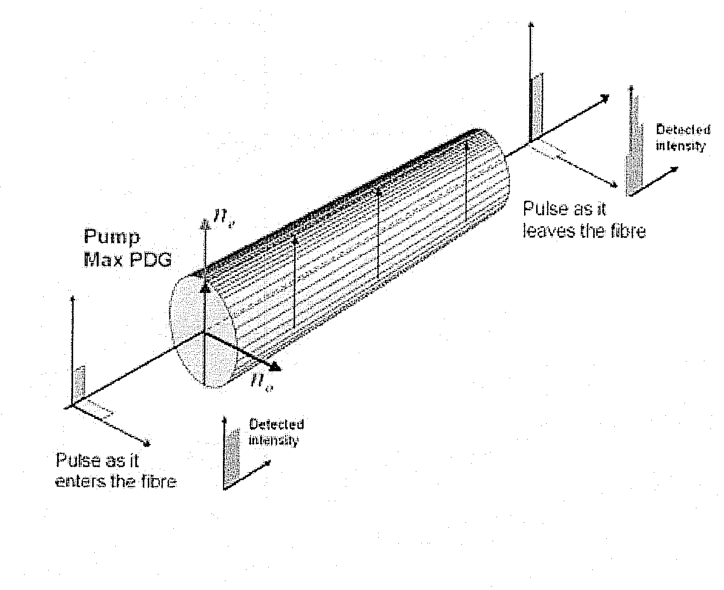
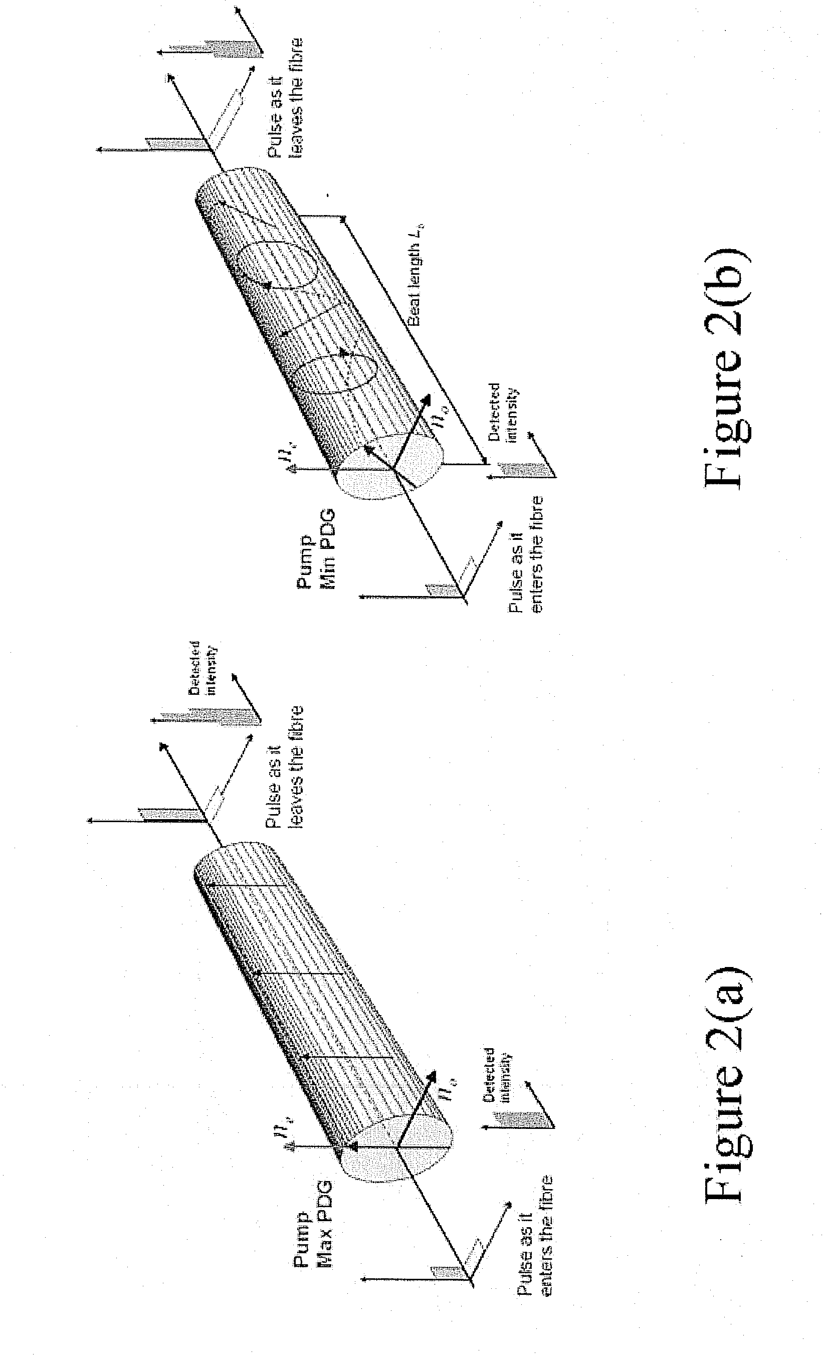
BACKGROUND[0001]An optical fiber Raman amplifier (FRA) is an optical amplifier based on Raman gain in which the Raman-active medium is an optical fiber. An input signal can be amplified while co- or counter-propagating with a pump beam, the wavelength of which is typically a few tens of nanometers shorter. The construction and operation of such amplifiers is very well known. The present invention primarily concerns the optical fiber used in such amplifiers.[0002]Polarization mode dispersion (PMD) in optical fibers is caused by geometry- and stress-based asymmetrical imperfections, and leads to optical pulse broadening due to different group velocities for pulses with orthogonal states of polarization (SOPs). Fiberspinning has been used to suppress PMD for some time, driven by the need to preserve the signal SOP especially for the development of sensing devices, such as magneto-optic current sensors utilizing the Faraday effect, fiber Bragg grating sensors insensitive to transverse ...
Claims
Application Information
Patent Timeline
Application Date:The date an application was filed.
Publication Date:The date a patent or application was officially published.
First Publication Date:The earliest publication date of a patent with the same application number.
Issue Date:Publication date of the patent grant document.
PCT Entry Date:The Entry date of PCT National Phase.
Estimated Expiry Date:The statutory expiry date of a patent right according to the Patent Law, and it is the longest term of protection that the patent right can achieve without the termination of the patent right due to other reasons(Term extension factor has been taken into account ).
Invalid Date:Actual expiry date is based on effective date or publication date of legal transaction data of invalid patent.

