Device for destroying sharp, pointed objects which is fitted with means for automatically unscrewing injecting needles and similar

a disposal device and sharp cutting technology, applied in the direction of infusion needles, refuse receptacles, applications, etc., can solve problems such as cuts or lesions, and achieve the effect of preventing accidental punctures

Inactive Publication Date: 2006-04-11
SARAITO
View PDF42 Cites 2 Cited by
  • Summary
  • Abstract
  • Description
  • Claims
  • Application Information

AI Technical Summary

Benefits of technology

[0024]Inside, the device has a tube or chimney located in the upper part of the solid contacts for the purpose of permitting the exhaust of gases produced by the melting required for disposing of the needles, lacking a ventilator or system forcing the gas exhaust, the gases being retained in the upper part of the tube by means of an activated carbon filter which prevents harmful particles from passing through which, due to the effect of the heat produced by melting the needle, go up this tube where a hollow, screw-on cap is placed on the end thereof.
[0028]The cylindrical part can also be prevented from turning when the part is going down through the tube, as this other tube has a system of one or two straight and hollow parallel rails on only one side of the tube or in both sides thereof in which the lug or lugs of the cylindrical part will be maximally separated from its ends opposite the lugs; thus, the cylindrical part will carry out an upward or downward movement without carrying out any type of rotation for those needles which are not of the “screw-on” system, and for those needles which are, inside the tube, a system of inner inclined rails or tracks will be provided, as previously indicated.

Problems solved by technology

It has been shown that, as these are blind recipients, in other words, provided with inlets through which the disposable material manufactured of metal is introduced, occasionally, the incorporated objects are placed inside in strange positions, remaining next to the inlet, which leads to causing cuts or lesions upon carrying out a new removal of these elements.

Method used


Image

  • Device for destroying sharp, pointed objects which is fitted with means for automatically unscrewing injecting needles and similar
  • Device for destroying sharp, pointed objects which is fitted with means for automatically unscrewing injecting needles and similar
  • Device for destroying sharp, pointed objects which is fitted with means for automatically unscrewing injecting needles and similar

Examples


Embodiment Construction

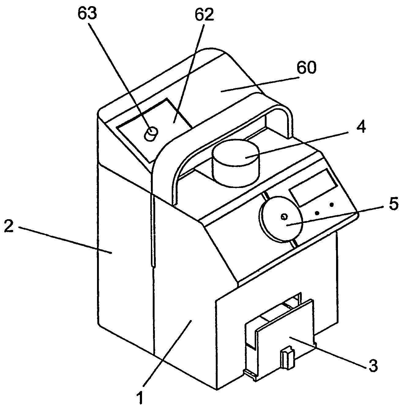
[0051]Following FIG. 7, it can be seen how the sharp cutting object disposal device provided with means for automatic unscrewing of venopuncture needles and the like, configured as a general body referenced with 1, showing a container for needleless syringes 2 in the rear part, and a drawer with a container neither shown nor referenced in the lower part referenced with 3, incorporated in the recipient deposit for needleless syringes, there is an additional and auxiliary recipient 70, preferably made of cardboard or tetra-pack, or from plastic bags provided with a suitable thickness, according to its application.

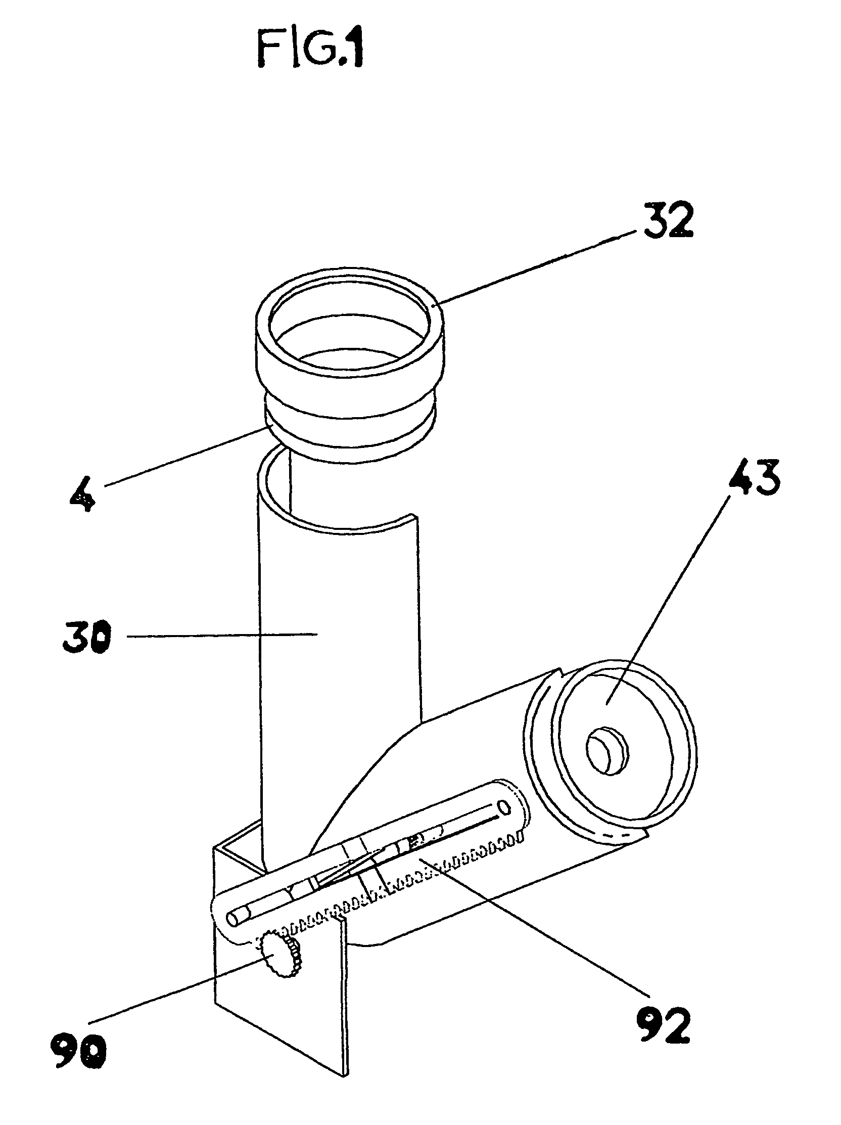
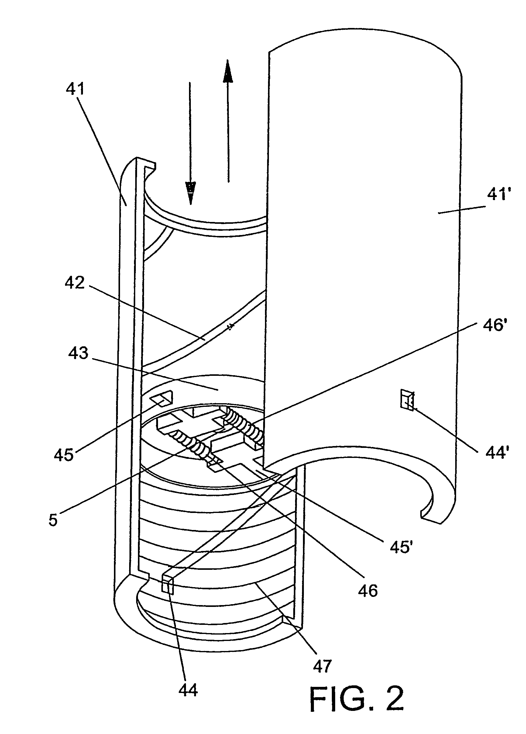
[0052]The invention is provided with an activated carbon filter 4 and an opening 5 intended for being used for introducing the sharp cutting objects.

[0053]The disposal of the sharp cutting objects, generally referenced with 40, is carried out as indicated in FIG. 13, the cylindrical part 43 pressed by the syringe 93, the latter moves downwards and in its movement, makes the t...


PUM

PropertyMeasurementUnit
angleaaaaaaaaaa
thicknessaaaaaaaaaa
pressureaaaaaaaaaa

Abstract

A sharp cutting object disposal device provided with means for automatic unscrewing of venopuncture needles and the like, consisting of a tube to which a pair of motors or a gear wheel are fixed, the wheel which, actuated by a geared part that upon sliding on the gear wheel, will cause the rotation of the latter and in turn, this gear wheel will move several gears which will make two cylindrical and solid contacts turn, carrying out the disposal of the needle by means of friction plus the passing of electric current, provided with a conduit inside for exhaust of gases produced by melting the needle, without needing ventilators or any other forced air system, in addition to having another tube for separating the needle from the “screw-on” type syringe during the same needle disposal operation, the inside of the drawer having a housing recipient for the needle wastes, and another recipient incorporated inside the container for housing the plastic needleless syringes or non-sharp hospital wastes, and inside this container, there is an ozone or ultraviolet valve for sterilizing the needles.

Description

BACKGROUND OF THE INVENTION[0001]The present specification refers to a Patent of Invention application regarding a sharp cutting object disposal device provided with means for automatic unscrewing of venopuncture needles and the like, whose evident purpose is based on being configured as a device fed by electric power, capable of massively disposing of sharp cutting object such as hypodermic needles, scalpel blades and other objects constituting single use surgical instruments, practically instantaneously.[0002]The invention acts with the collaboration of one or two motors fed by electric current, powered with the electric current passing through their rotating contacts, or through a gear wheel which rotates when a part which is also geared moves over the former, on whose upper part a cylinder is fixed moving up or down due to the pressure of a syringe with its needle.[0003]The invention is provided with a device intended for exhausting the gases produced inside due to the disposal ...

Claims


Application Information

Patent Timeline
Patent Type & Authority Patents(United States)
IPC IPC(8): B23P19/00B65F1/00A61G12/00A61MA61M5/32
CPCA61M5/3278A61M2005/3208A61M2005/3283Y10T29/534Y10T29/49716Y10T29/49821Y10T29/53443Y10T29/53339Y10T29/49822A61M5/178
Inventor DUENAS SANCHEZ, SILVERIO
Owner SARAITO
Why Eureka
Try Eureka