Particle beam irradiation system and method of adjusting irradiation apparatus

a particle beam and irradiation system technology, applied in the direction of x-ray/gamma-ray/particle irradiation therapy, radiation therapy, radiation dose distribution, etc., can solve the problem of difficulty in maintaining a high degree of radiation dose distribution uniformity in the direction of depth, and achieve the effect of increasing the uniformity of radiation dose distribution

Inactive Publication Date: 2006-04-11
HITACHI LTD
View PDF18 Cites 231 Cited by
  • Summary
  • Abstract
  • Description
  • Claims
  • Application Information

AI Technical Summary

Benefits of technology

[0006]It is therefore an object of the present invention to provide a particle beam irradiation system that is capable of increasing the uniformity of radiation dose distribution in the direction of the depth of a diseased part.
[0007]To achieve the above object, the present invention provides an irradiation apparatus in which at least either a scattering device or a Bragg peak spreading device is mounted in such a manner that the device is movable in the direction of charged particle beam propagation. Since at least either the scattering device or Bragg peak spreading device can move in the direction of charged particle beam propagation, it is possible to increase the uniformity of radiation dose distribution for the irradiation target that is exposed to a charged particle beam.
[0008]Preferably, at least one of a scattering device, a range adjustment device, and a Bragg peak spreading device is mounted in the irradiation apparatus in such a manner that the device is movable in the direction of charged particle beam propagation. Since at least either one of the scattering device, range adjustment device, and Bragg peak spreading device can move in the direction of charged particle beam propagation, it is possible to increase the uniformity of radiation dose distribution for the irradiation target that is exposed to a charged particle beam.

Problems solved by technology

In a particle beam therapy system containing the aforementioned conventional irradiation apparatus, however, it has been difficult to maintain a high degree of radiation dose distribution uniformity in the direction of the depth while keeping a high radiation dose level particularly for a bulky diseased part (region targeted for irradiation).

Method used


Image

  • Particle beam irradiation system and method of adjusting irradiation apparatus
  • Particle beam irradiation system and method of adjusting irradiation apparatus
  • Particle beam irradiation system and method of adjusting irradiation apparatus

Examples


first embodiment

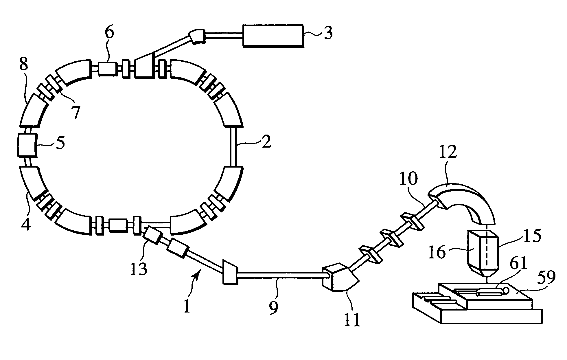
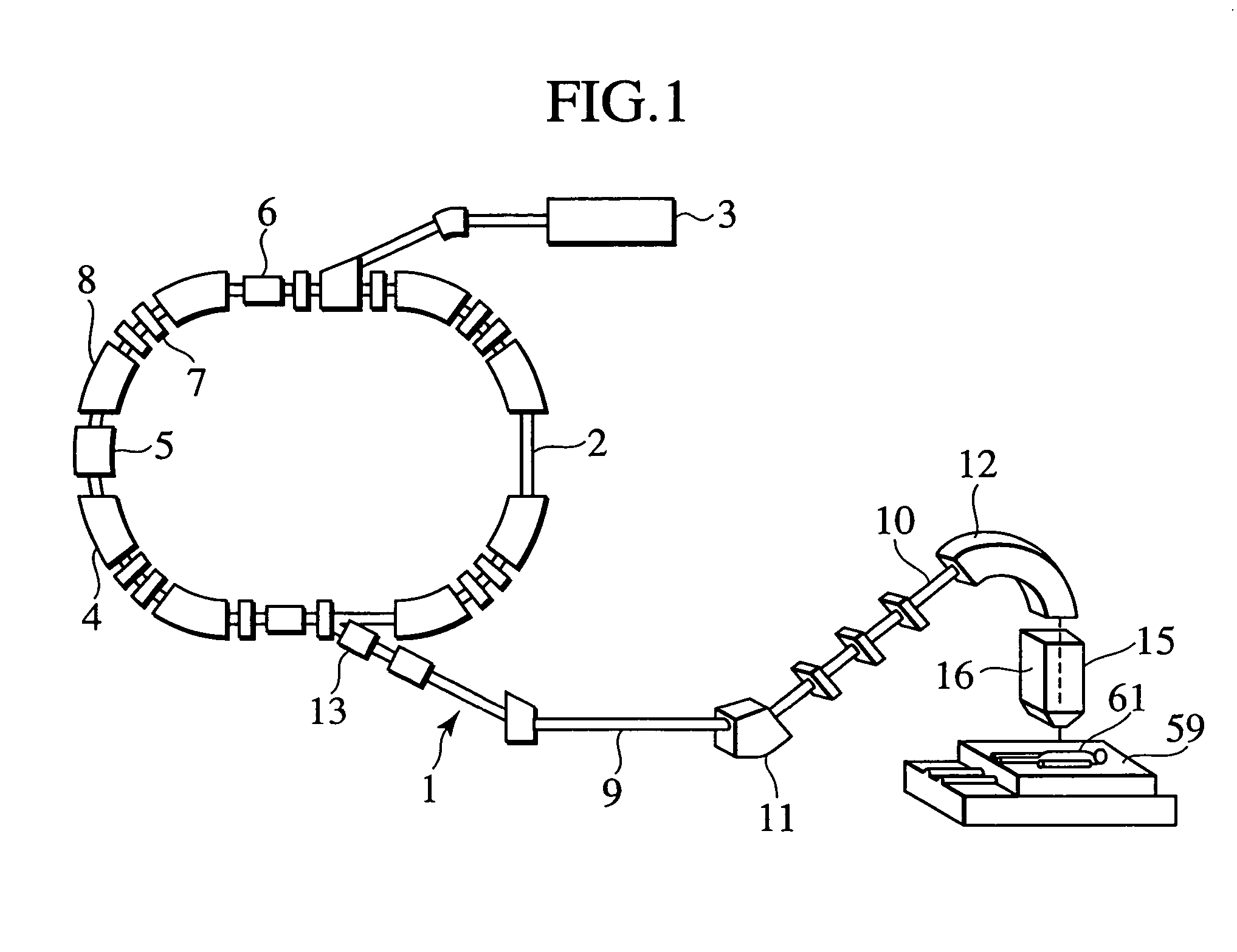
[0028]A particle beam therapy system according to a preferred embodiment of the present invention will now be described with reference to FIG. 1. The particle beam therapy system 1 according to the present embodiment comprises a charged particle beam generation apparatus 2 and an irradiation apparatus 15. The charged particle beam generation apparatus 2 includes an ion source (not shown), a preaccelerator 3, and a synchrotron 4. Ions generated by the ion source (e.g., proton ions or carbon ions) are accelerated by the preaccelerator 3 (e.g., linear accelerator). An ion beam emitted from the preaccelerator 3 enters the synchrotron 4. In the synchrotron 4, the ion beam is energized and accelerated by high-frequency power, which is applied by a high-frequency acceleration cavity 5. After the energy of the ion beam circulating within the synchrotron 4 is raised to a preselected level, an outgoing high-frequency application device 6 applies a high frequency to the ion beam. Upon high-fre...

second embodiment

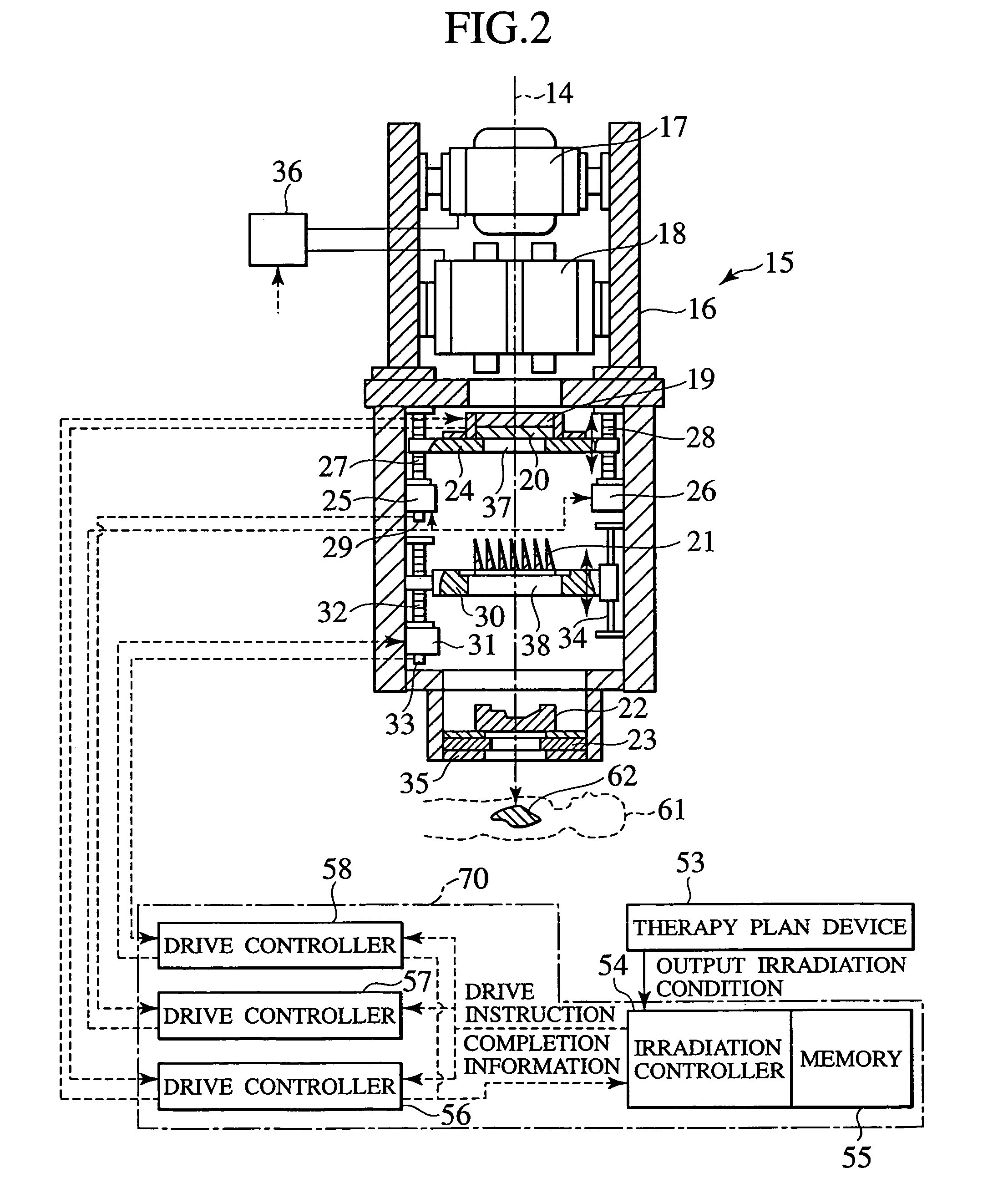
[0056]A particle beam therapy system according to a second embodiment of the present invention will now be described. The particle beam therapy system according to the present embodiment is configured so that the irradiation apparatus 15 in the particle beam therapy system 1 shown in FIG. 1 is replaced by an irradiation apparatus 15A shown in FIG. 8. The irradiation apparatus 15A differs from the irradiation apparatus 15 in positions of the SOBP device 21 and the components associated with it. As shown in FIG. 8, the irradiation apparatus 15A is configured so that the SOBP device 21 is positioned upstream of the first scanning magnet 17. The support member 30, AC servomotor 31, ball screw 32, encoder 33, and linear guide 34 are also positioned upstream of the first scanning magnet 17 and mounted within the casing 16. A rotary wheel type SOBP filter may be used as the SOBP device.

[0057]The ion beam passing through a thin portion of the SOBP device 21 is high in energy. Therefore, the...

third embodiment

[0061]The foregoing embodiments relate to a particle beam therapy system that is based on a wobbling type irradiation apparatus. A third embodiment of the present invention, that is, a particle beam therapy system based on a scatterer type irradiation apparatus, will now be described. The particle beam therapy system according to the third embodiment is such that the irradiation apparatus 15 in the particle beam therapy system 1 shown in FIG. 1 is replaced by irradiation apparatus 15B, which is a scatterer type, first irradiation apparatus shown in FIG. 11. The particle beam therapy system according to the present embodiment does not include a drive controller 58. The irradiation apparatus 15B includes a scattering device 19 (first scatterer), a scattering device 63 (second scatterer), a SOBP device 21, and a range adjustment device 20, which are mounted within a casing 16 and sequentially arranged from upstream to downstream of ion beam propagation. The casing 16 includes a bolus r...


PUM


Abstract

The present invention provides an increased degree of uniformity of radiation dose distribution for the interior of a diseased part. A particle beam therapy system includes a charged particle beam generation apparatus and an irradiation apparatus. An ion beam is generated by the charged particle beam generation apparatus. The irradiation apparatus exposes a diseased part to the generated ion beam. A scattering device, a range adjustment device, and a Bragg peak spreading device are installed upstream of a first scanning magnet and a second scanning magnet. The scattering device and the range adjustment device are combined together and moved along a beam axis, whereas the Bragg peak spreading device is moved independently along the beam axis. The scattering device moves to adjust the degree of ion beam scattering. The range adjustment device moves to adjust ion beam scatter changes caused by an absorber thickness adjustment. The Bragg peak spreading device moves to adjust ion beam scatter changes arising out of an SOBP device. These adjustments provide uniformity of radiation dose distribution for the diseased part.

Description

[0001]This application is a continuation of application Ser. No. 10 / 671,613, filed on Sep. 29, 2003 now abandoned, which is a continuation of application Ser. No. 10 / 455,497, filed on Jun. 6, 2003 now U.S. Pat. No. 6,777,700 which claims priority to Japanese Patent Application Serial No. 2002-170778, filed on Jun. 12, 2002, which are hereby incorporated by reference in their entirety.BACKGROUND OF THE INVENTION[0002]The present invention relates to a particle beam irradiation system, and more particularly to a particle beam irradiation system for use as a particle beam therapy system for exposing a diseased part to a proton, carbon, or other charged particle beam for therapy purposes, a material irradiation system for exposing a material to a charged particle beam, a food irradiation system for exposing food to a charged particle beam, or a radioisotope production system based on a charged particle beam.[0003]A conventional particle beam therapy system comprises a charged particle b...

Claims


Application Information

Patent Timeline
Patent Type & Authority Patents(United States)
IPC IPC(8): H05H9/00G21K1/093A61N5/10G21K5/04G21K1/10G21K3/00G21K5/00H05H13/04
CPCA61N5/1042G21K5/04G21K1/10A61N2005/1087A61N2005/1095
Inventor YANAGISAWA, MASAKIAKIYAMA, HIROSHIMATSUDA, KOJIFUJIMAKI, HISATAKA
Owner HITACHI LTD
Why Eureka
Try Eureka