Electronic camera
a technology of electronic cameras and cameras, applied in the field of electronic cameras, can solve the problems of low image quality, low image quality, and large weight of the shooting lens, and achieve the effects of reducing the worst value of release time lag, and obtaining image data reliably
- Summary
- Abstract
- Description
- Claims
- Application Information
AI Technical Summary
Benefits of technology
Problems solved by technology
Method used
Image
Examples
first embodiment
(First Embodiment)
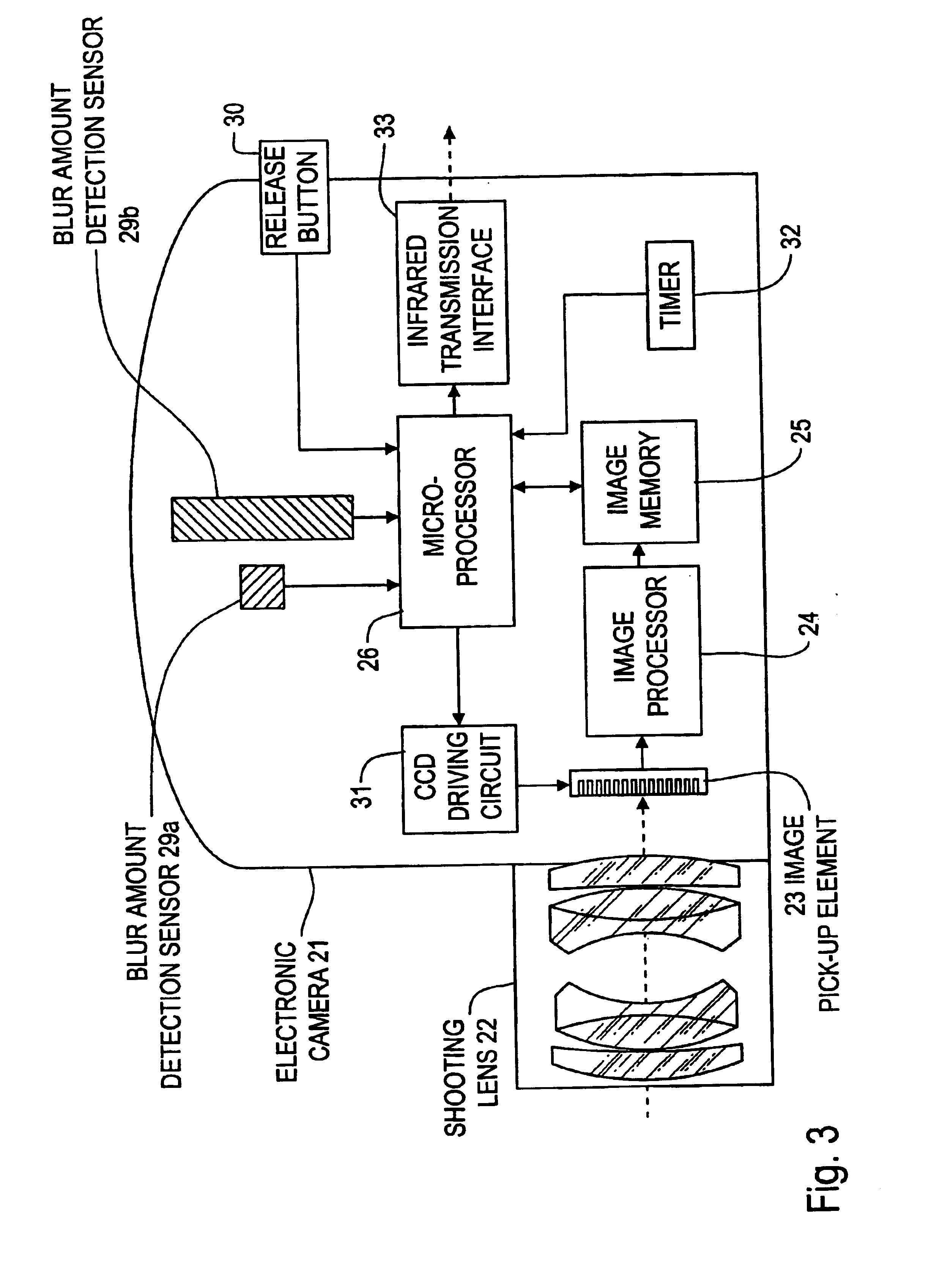
[0081]FIG. 3 is a block diagram which shows the first embodiment. Moreover, the first embodiment corresponds to the invention of claims 1, 2, 4, 5 and 7.
[0082]In FIG. 3, a shooting lens 22 is provided at the front face of the electronic camera 21. The light receiving face of an image pick-up element 23 is arranged on the image space side of the shooting lens 22.
[0083]The image output of this image pick-up element 23 is directly stored in the image memory 25 via an image processor 24 which performs color signal processing, A / D conversion, γ correction, image compression and the like. Other than this, in the image memory 25, reading and writing of the data are performed via the data bus of the microprocessor 26.
[0084]Moreover, blur amount detecting sensors 29a and 29b that are made of an angular speed sensor such as a piezoelectric gyro are arranged within the case of the electronic camera 21. The blur amount detecting sensor 29a detects the blur amount in the vertic...
second embodiment
(Second Embodiment)
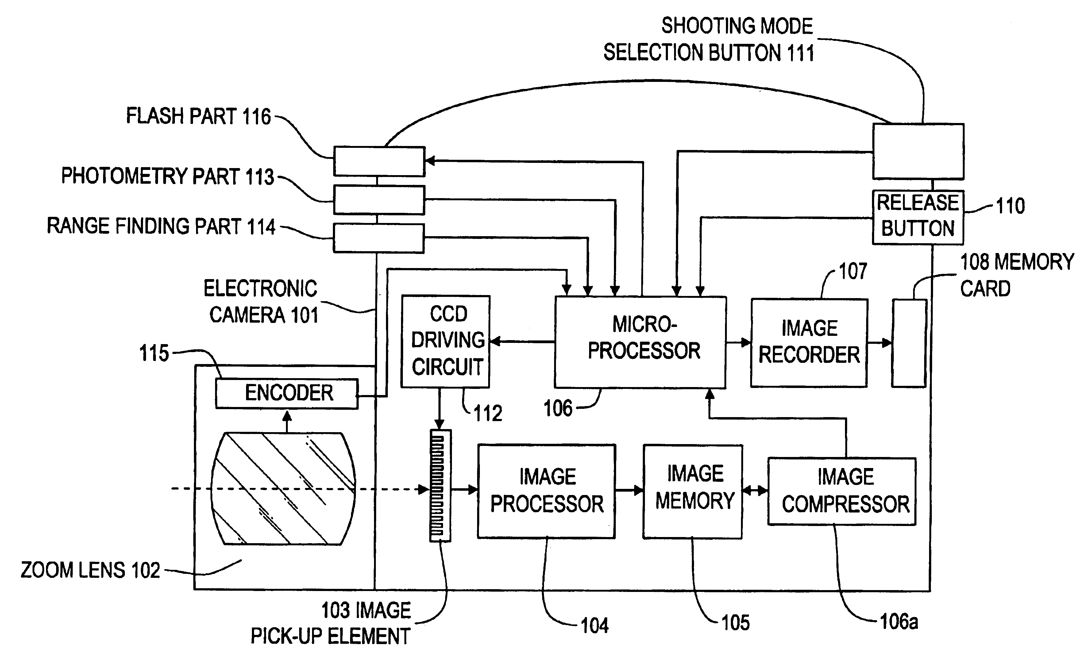
[0108]FIG. 6 is a block diagram which shows the second embodiment. Moreover, the second embodiment corresponds to the invention that is described in claims 1, 3, 7 and 10.
[0109]In FIG. 6, a shooting lens 42 is provided on a front face of the electronic camera 41. The light receiving face of an image pick-up element 43 is arranged on the image space side of the shooting lens 42.
[0110]The image output from the image pick-up element 43 is connected to the data input of the image memory 45 via the image processor 44 which performs color signal processing, A / D conversion, γ correction and the like. Meanwhile, the data output of the image memory 45 is connected to the data input of the microprocessor 46.
[0111]A memory card 48 is detachably connected to the data output terminal of the microprocessor 46 via the image recording part 47.
[0112]Meanwhile, blur amount detecting sensors 49a and 49b that are composed of an angular speed sensor such as a piezoelectric gyro are ar...
third embodiment
(The Third Embodiment)
[0137]FIG. 8 is a block diagram showing the third embodiment.
[0138]In FIG. 8, a shooting lens 62 is fixed at a front surface of the electronic camera 61. The light-receiving face of an image pick-up element 63 is disposed on the image space side of the shooting lens 62.
[0139]The image output of the image pick-up element 63 is given to a microprocessor 65 through an image processor 64, which performs color signal processing, A / D conversion, γ correction, and the like. Furthermore, an image memory 66 is connected to the data bus of the microprocessor 65.
[0140]Additionally, a memory card 68 is detachably connected to the data output terminal of the microprocessor 65 through an image recorder 67.
[0141]Furthermore, the blur amount detection sensors 69a and 69b comprising an angular speed sensor such as a piezoelectric gyro are disposed inside of the case of the electronic camera 61. The outputs of the blur amount detection sensors 69a and 69b are respectively connec...
PUM
 Abstract
Description
Claims
Application Information
 - R&D
- Intellectual Property
- Life Sciences
- Materials
- Tech Scout
- Unparalleled Data Quality
- Higher Quality Content
- 60% Fewer Hallucinations
Browse by: Latest US Patents, China's latest patents, Technical Efficacy Thesaurus, Application Domain, Technology Topic, Popular Technical Reports.
© 2025 PatSnap. All rights reserved.Legal|Privacy policy|Modern Slavery Act Transparency Statement|Sitemap|About US| Contact US: help@patsnap.com


