
Moving-picture coding and decoding method and apparatus with reduced computational cost

a technology of moving pictures and computational cost reduction, applied in the field of moving picture coding and decoding methods and apparatuses, can solve the problems of high computational cost, other costs, and significant cost in the idct, and achieve the effect of reducing memory requirements

Inactive Publication Date: 2006-04-11
RAKUTEN GRP INC
View PDF16 Cites 72 Cited by
  • Summary
  • Abstract
  • Description
  • Claims
  • Application Information

AI Technical Summary

Benefits of technology

The present invention aims to reduce the memory requirements and processing requirements of a moving-picture decoder and coder. It achieves this by performing an IDCT with resolution conversion to generate a first picture signal with reduced resolution, and then adding the first and second picture signals to obtain an output picture signal with reduced resolution. The invention also includes a method for compressing the predictively coded moving-picture signal and storing it in a memory. Additionally, the invention provides a method for performing a one-dimensional IDCT in two modes with full and reduced resolution, and selecting the appropriate results for output. The invention also provides coding and decoding apparatus employing these methods.

Problems solved by technology

A general problem in this and other similar coding systems is their high computational cost.
A significant part of the cost occurs in the IDCT, which involves many multiplication operations, the efficient performance of which requires extra hardware and software.
Another cost occurs because of the large amount of semiconductor memory required for storing the reference pictures used in motion compensation.
The many accesses required to this memory are yet another computational cost.
These costs are particularly great when the transmitted picture is a high-definition television (HDTV) picture.

Method used


Image

  • Moving-picture coding and decoding method and apparatus with reduced computational cost
  • Moving-picture coding and decoding method and apparatus with reduced computational cost
  • Moving-picture coding and decoding method and apparatus with reduced computational cost

Examples


first embodiment

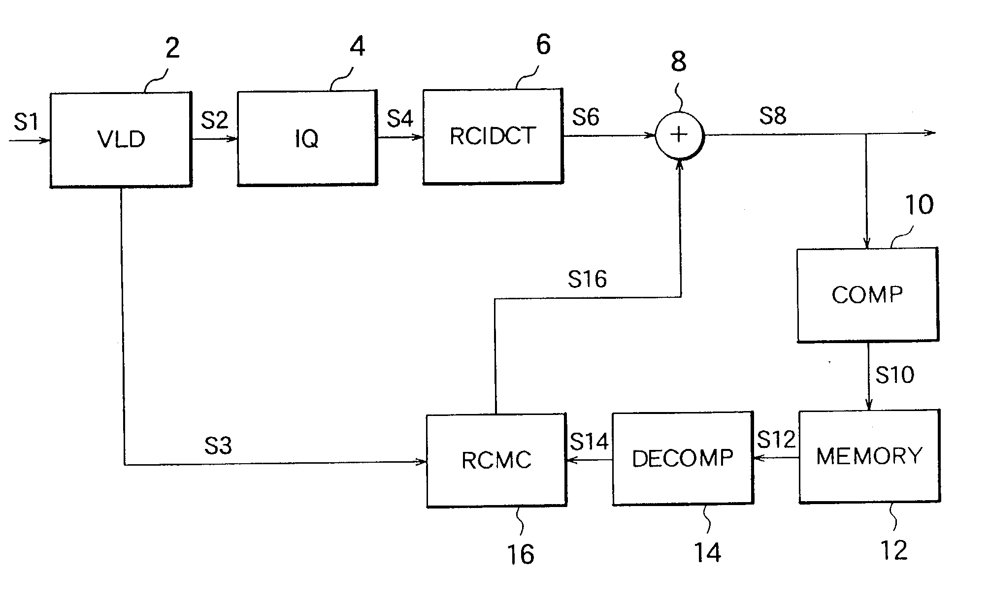
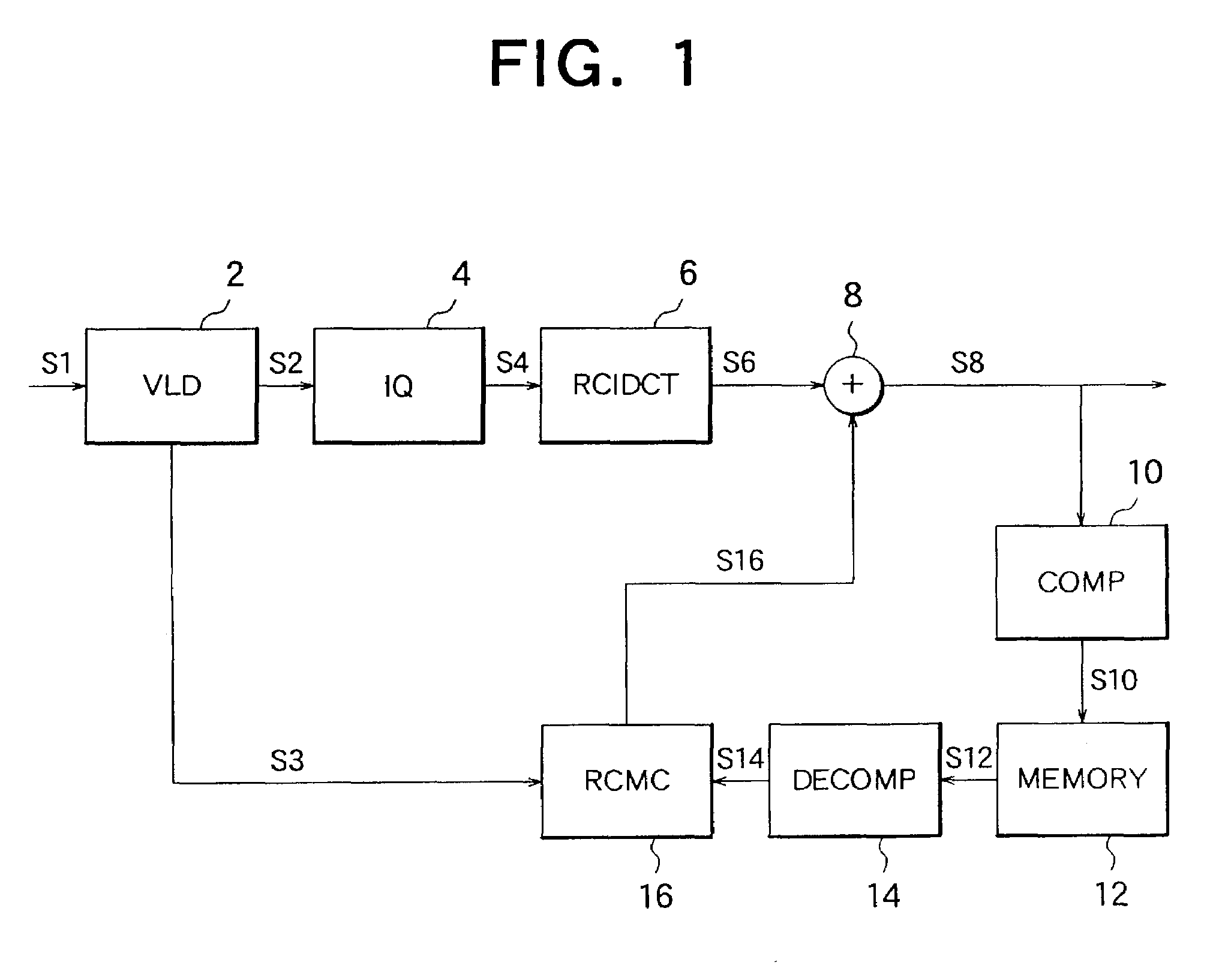
[0102]Next, the operation of the first embodiment will be described.

[0103]The variable-length decoder 2 and inverse quantizer 4 operate according to conventional variable-length decoding and dequantization procedures, detailed descriptions of which will be omitted.

[0104]The resolution-converting IDCT processor 6 operates, for example, as follows. First, the values y(k) defined in equation (7) above are obtained by performing matrix operation (8) on an eight-by-eight block of DCT coefficients. Each y(k) is equal to the average value of two consecutive pixel values x(2k) and x(2k+1), so this operation is equivalent to a horizontal IDCT followed by horizontal down-sampling by a factor of two. Next, a conventional vertical IDCT is carried out on the down-sampled values to obtain the first picture signal S6, without further down-sampling. The total amount of picture data in the first picture signal S6 is thus reduced by a factor of two, and the amount of necessary computation is also red...

second embodiment

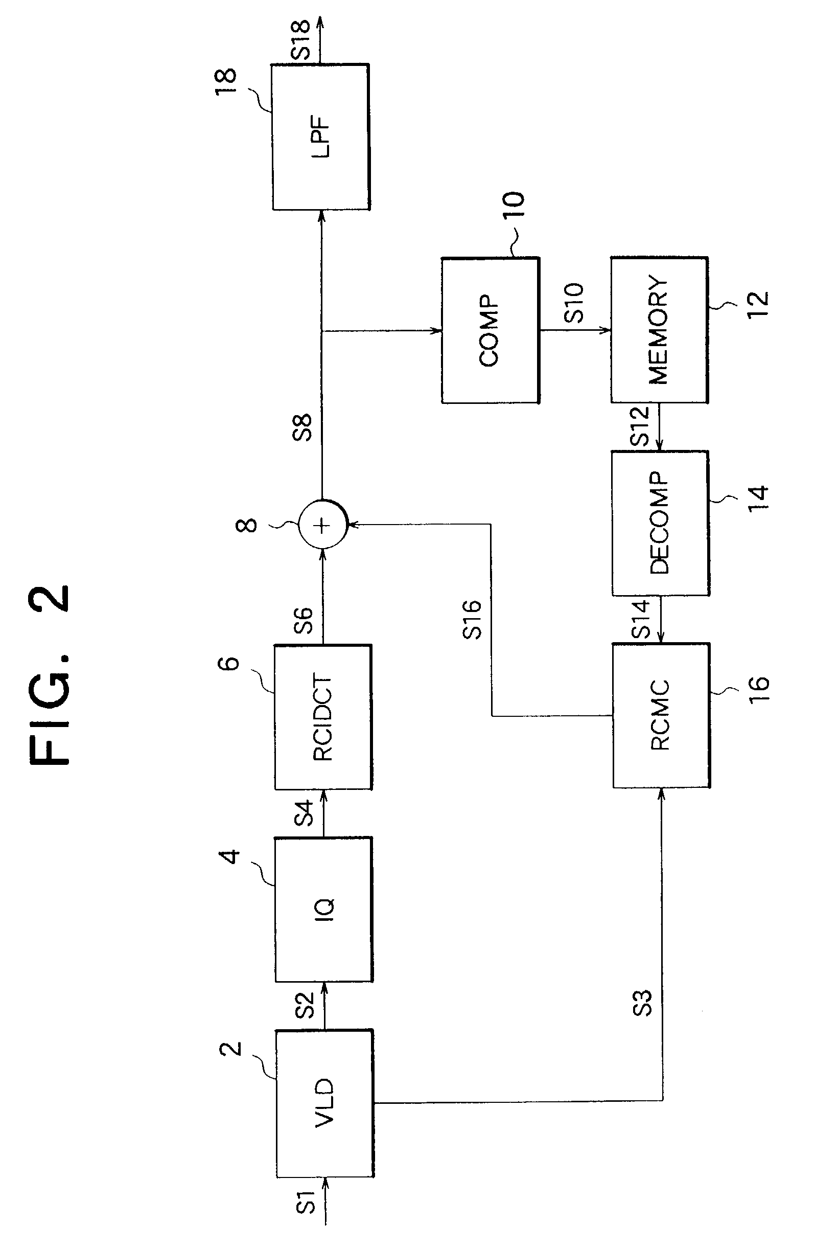
[0115]Next, a second embodiment will be described.

[0116]Referring to FIG. 2, the second embodiment adds a low-pass filter (LPF) 18 to the configuration of the first embodiment. The low-pass filter 18 filters the output picture signal S8 to obtain a filtered output signal S18. The low-pass filter 18 operates only on pictures coded by intra-frame coding, and on the succeeding few predictively coded pictures, using predetermined initial filter coefficients for the intra-frame-coded picture, and successively weaker filter coefficients for the succeeding few predictively coded pictures or inter-frames.

[0117]As one example of filter coefficients that may be used, in an intra-frame-coded picture or intra-frame, if X, Y, and Z are three consecutive pixel values, the filter 18 replaces Y by the following value

(X+2Y+Z) / 4

[0118]The filter coefficients (1 / 4, 2 / 4, 1 / 4) in this case can be expressed more compactly by the notation (1, 2, 1) / / 4. An example of the complete set of coefficients used by...

third embodiment

[0126]Next, a third embodiment will be described.

[0127]Referring to FIG. 4, the third embodiment is a moving-picture coder comprising a subtractor 24, a DCT processor 26, a quantizer (Q) 28, a variable-length coder (VLC) 30, an inverse quantizer 32, a resolution-converting IDCT processor 34, an adder 36, a memory 38, a resolution-converting motion estimator (RCME) 40, and a resolution-converting motion compensator (RCMC) 42.

[0128]The subtractor 24 receives a digitized moving-picture input signal S22 comprising pictures to be coded by intra-frame or inter-frame coding. For inter-frame coding, the subtractor 24 subtracts a predicted picture S42 supplied by the resolution-converting motion compensator 42 and outputs a difference picture signal S24. For intra-frame coding, this picture signal S24 is identical to the input signal S22.

[0129]The DCT processor 26 performs a conventional discrete cosine transform on the picture signal S24 received from the subtractor 24, without performing r...


PUM


Abstract

A coded moving-picture signal is decoded by a resolution-converting motion compensation process and a resolution-converting inverse discrete cosine transform, both of which decrease the resolution of the picture, thereby reducing the amount of reference picture data that has to be stored and accessed. The reference picture data may also be stored in a compressed form. The resolution conversion and compression processes may also be used in the coding of the moving-picture signal. The resolution-converting inverse discrete cosine transform may be performed by output of intermediate results that have not been combined by addition and subtraction in a butterfly computation.

Description

[0001]This application is a divisional of U.S. application Ser. No. 09 / 435,488, filed Nov. 8, 1999 now U.S. Pat. No. 6,584,154.BACKGROUND OF THE INVENTION[0002]The present invention relates to methods and apparatus for coding and decoding moving pictures.[0003]Moving pictures are transmitted in digital form in a variety of systems, which will soon include digital television broadcasting systems. To reduce the quantity of transmitted data, digitized moving pictures must be coded at the transmitter and decoded at the receiver. The MPEG-2 coding system standardized by the Moving Picture Experts Group is widely used. In this system, a moving picture is coded predictively by a series of steps involving motion estimation, motion compensation, a discrete cosine transform (DCT), quantization, and variable-length coding. The coded data are decoded by a reverse process involving variable-length decoding, inverse quantization or dequantization, an inverse discrete cosine transform (IDCT), and ...

Claims


Application Information

Patent Timeline
Patent Type & Authority Patents(United States)
IPC IPC(8): H04N7/12G06T9/00H04N7/26H04N7/36H04N7/46H04N7/50
CPCH04N19/51H04N19/59H04N19/115H04N19/61H04N19/117H04N19/126H04N19/132H04N19/136H04N19/154H04N19/157H04N19/80H04N19/428H04N19/43H04N19/523H04N19/122
Inventor WU, ZHIXIONG
Owner RAKUTEN GRP INC
Learn More