Layover heating system for a locomotive

a technology for locomotives and heating systems, applied in the direction of engine starters, lighting and heating apparatus, heating types, etc., can solve the problems of affecting the operation of the engine, so as to achieve the effect of reducing the fluid flow through the radiator

Inactive Publication Date: 2006-04-18
ELECTRO-MOTIVE DIESEL
View PDF7 Cites 7 Cited by
  • Summary
  • Abstract
  • Description
  • Claims
  • Application Information

AI Technical Summary

Benefits of technology

[0031]A layover, heating method for a locomotive engine adapted for use in connection with a locomotive cooling system having a water tank, an engine, a radiator and an oil cooler is also provided. The method comprises pumping fluid from the water tank through a layover heater. The fluid in the heater is then heated. The heated fluid is provided then to the engine and to the oil cooler. An orifice for controlling the flow of fluid to minimize fluid flow through the radiator is provided.

Problems solved by technology

On the other hand, if the heat transferred to the coolant is low and the ambient air temperature is low, there can be a possibility for the coolant to freeze.
This is not desirable as it can create freeze-damage on components, particularly on radiators.
This alternative ensures the proper operation of the engine but has undesirable characteristics.
First, idling consumes fuel even when the locomotive is not in use.
In some business case studies, the cost of fuel consumed in idle operation for one year is estimated to be larger than the cost of developing alternative systems.
Second, idling reduces the effective life of the engine.
Parking the locomotive inside a heated building is limited by the available buildings.
In most cases, it is not a practical solution.
This option also is not desirable by railroads as warming up the locomotive inside the building takes a long time.
Moreover, a suitable building is not available in most locations.
However, it has two major drawbacks, namely, (a) it still requires the operation of the large locomotive engine (which is costly and reduces engine life), and (b) it is noisy and creates noise pollution.
Starting and operating the locomotive engine at an urban environment, particularly during night hours, is restricted by local ordinances.
Therefore, it would not be possible to start the engine.
The size, weight and cost of engine start-up systems go up very rapidly with decreasing start-up temperature.
Heating the oil directly with an electric heater has some limitations.
If this is permitted, it will start the oxidation of the oil even at low temperatures and consequently reduce the oil life to unacceptable levels.
This in turn would increase the size of the electric heater necessary to do the job and become impractical.
a) To control the proper clearance at engine liners. With decreasing ambient temperature, the liner will shrink and reduce the clearance between the liner and piston (rings). If the engine is started with liners that are at a temperature below a permissible low value, this will cause excessive wear and tear both on the rings and the liner. It will require a much higher start-up power and increase the size and cost of the starting system. It may also cause liner scuffing.
b) If the coolant is permitted to freeze, particularly within radiator tubes and liner passages, it may cause permanent damage to the tubes and other components.
c) At low enough temperatures, the water-glycol mixtures behave like a jelly and would not flow as easily. Hence, the coolant pump operation can be hindered at the start-up if the coolant temperatures are permitted to be too low.
d) The combustibility of the fuel injected into the engine cylinder depends on the air temperature in the cylinder. Heating the engine coolant will in turn heat the liner and through the liner, the air trapped in the cylinder. If the coolant is not heated, and at low ambient air temperatures, the fuel may not combust and starting the engine may not be possible.
e) At some low ambient temperatures, the fuel is not burned completely, leading to phenomena called “white smoke”. Heating the engine coolant tends to reduce and eliminate the engine white smoke and start-up emissions.
At some applications where the ambient temperature becomes very cold, heating the locomotive cab also becomes an important issue for the crew.

Method used


Image

  • Layover heating system for a locomotive
  • Layover heating system for a locomotive
  • Layover heating system for a locomotive

Examples


Embodiment Construction

[0042]The following description of the preferred embodiment(s) is merely exemplary in nature and is in no way intended to limit the invention, its application, or uses.

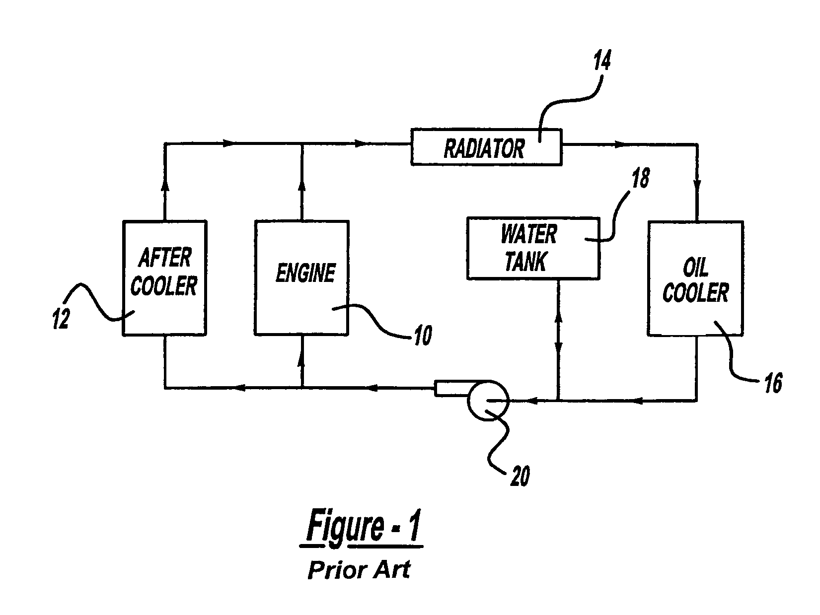
[0043]In FIG. 1, the schematic arrangement of a conventional cooling system for a locomotive diesel engine is shown. These systems were used extensively up to about 1980s. The cooling pump circulates the coolant in the direction of the arrows through the engine 10 (and a parallel aftercooler 12), through the radiators 14 and the oil cooler 16. A water tank 18 supplies the water to the system and maintains pressure head to the water pump 20. Other engine components in need of heating or cooling by the engine water (such as air compressor, fuel oil preheater, etc.) can be installed on this loop at appropriate locations. An important characteristic of this system is the fact that the coolant temperature at the inlet of the engine is the same as at the inlet to the aftercooler core. This limits the amount of air cooling a...


PUM


Abstract

A layover heating system (89) for a locomotive is provided. The layover heating system (89) is adapted to be used in conjunction with a conventional locomotive cooling systems. The layover heating system (89) includes a water tank and pump (90). A layover heater (92) heats fluid in the layover heating system (89). An orifice (98) is provided to control the flow Of fluid in the layover system (89) to generally balance the pressure on either side of the locomotive radiator. In this manner, fluid flow through the radiator is minimized, minimizing heat loss at the radiator. A variable orifice may be used that is adjustable in response to a signal generated from pressure sensors on each side of the radiator and processed by a central processing unit.

Description

CROSS-REFERENCE TO RELATED APPLICATIONS[0001]This application claims the benefit of U.S. Provisional Application No. 60 / 287,117 filed Apr. 27, 2001.FIELD OF THE INVENTION[0002]The present invention relates to a heating system for a locomotive. More specifically, the present invention relates to a layover heating system for a locomotive.BACKGROUND OF THE INVENTION[0003]In most modern diesel-electric locomotives, the diesel engine drives the electric generators which in turn powers the electric motors that drive the locomotive wheels. The engine is typically a turbocharged diesel engine with turbochargers and aftercoolers. Every diesel electric locomotive has an engine cooling system.[0004]The engine cooling system circulates the liquid coolant through the engine cooling loop to remove heat from the engine for two major reasons: (1) To keep the temperatures of the engine parts within allowable limits for reliability and durability and (2) to remove the heat from the incoming engine ai...

Claims


Application Information

Patent Timeline
Patent Type & Authority Patents(United States)
IPC IPC(8): B60H1/02F01P5/10F01P7/14F01P7/16F01P11/02F01P11/20F02N19/10
CPCF01P7/165F01P11/20F02N19/10F01P11/029F01P2005/105F01P2007/143F01P2007/146F01P2025/04F01P2025/06F01P2037/02F01P2060/02F01P2060/04F01P2060/18F01P2023/08
Inventor UZKAN, TEOMAN
Owner ELECTRO-MOTIVE DIESEL
Why Eureka
Try Eureka