Electrohydraulic valve actuator assembly

a technology of actuator assembly and electric motor, which is applied in the direction of valve arrangement, machines/engines, non-mechanical valves, etc., can solve the problems of high seating velocity-induced noise, low repeatability from cycle to cycle and cylinder, and high energy consumption, so as to improve engine performance and fuel economy, improve valvetrain stability without sacrificing dynamic performance, and precise motion

Inactive Publication Date: 2005-12-06
GM GLOBAL TECH OPERATIONS LLC
View PDF5 Cites 4 Cited by
  • Summary
  • Abstract
  • Description
  • Claims
  • Application Information

AI Technical Summary

Benefits of technology

[0008]An advantage of the present invention is that the valve actuator assembly has dual hydraulic feedback for precise motion. Another advantage is that the valve actuator assembly provides improved valvetrain stability without sacrificing dynamic performance. The valve actuator assembly also enables improved engine performance and fuel economy and lower engine emissions by improved valve control. The valve actuator assembly minimizes energy consumption by optimized flow control, a simple spool valve and efficient valve control to minimize throttling of the fluid flow. The spool valve and the first and second orifices create dual feedback to provide both precise valve lift control and soft valve landing. Another advantage of the valve actuator assembly of the present invention is that it is of relatively small size and easy to package in an engine. Another advantage of the present invention is that it has relatively less contents and therefore lower cost.

Problems solved by technology

Such actuators often result high energy consumption, low repeatability from cycle to cycle and cylinder to cylinder and high seating velocity-induced noise.
Some valve actuator assemblies do not provide full capability of variable lift.
They may also be of relatively high cost and have large packaging size.

Method used


Image

  • Electrohydraulic valve actuator assembly
  • Electrohydraulic valve actuator assembly
  • Electrohydraulic valve actuator assembly

Examples


Embodiment Construction

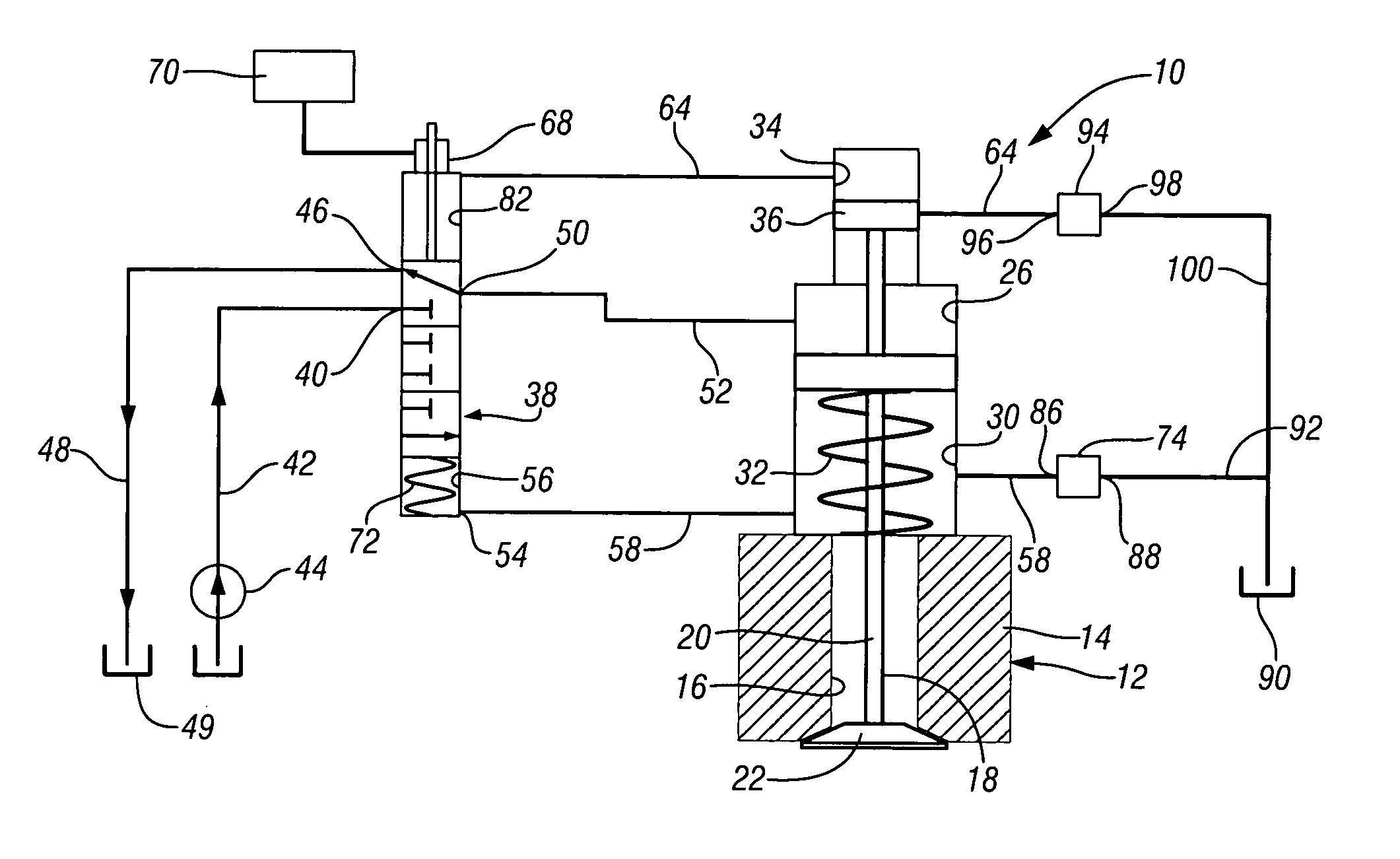
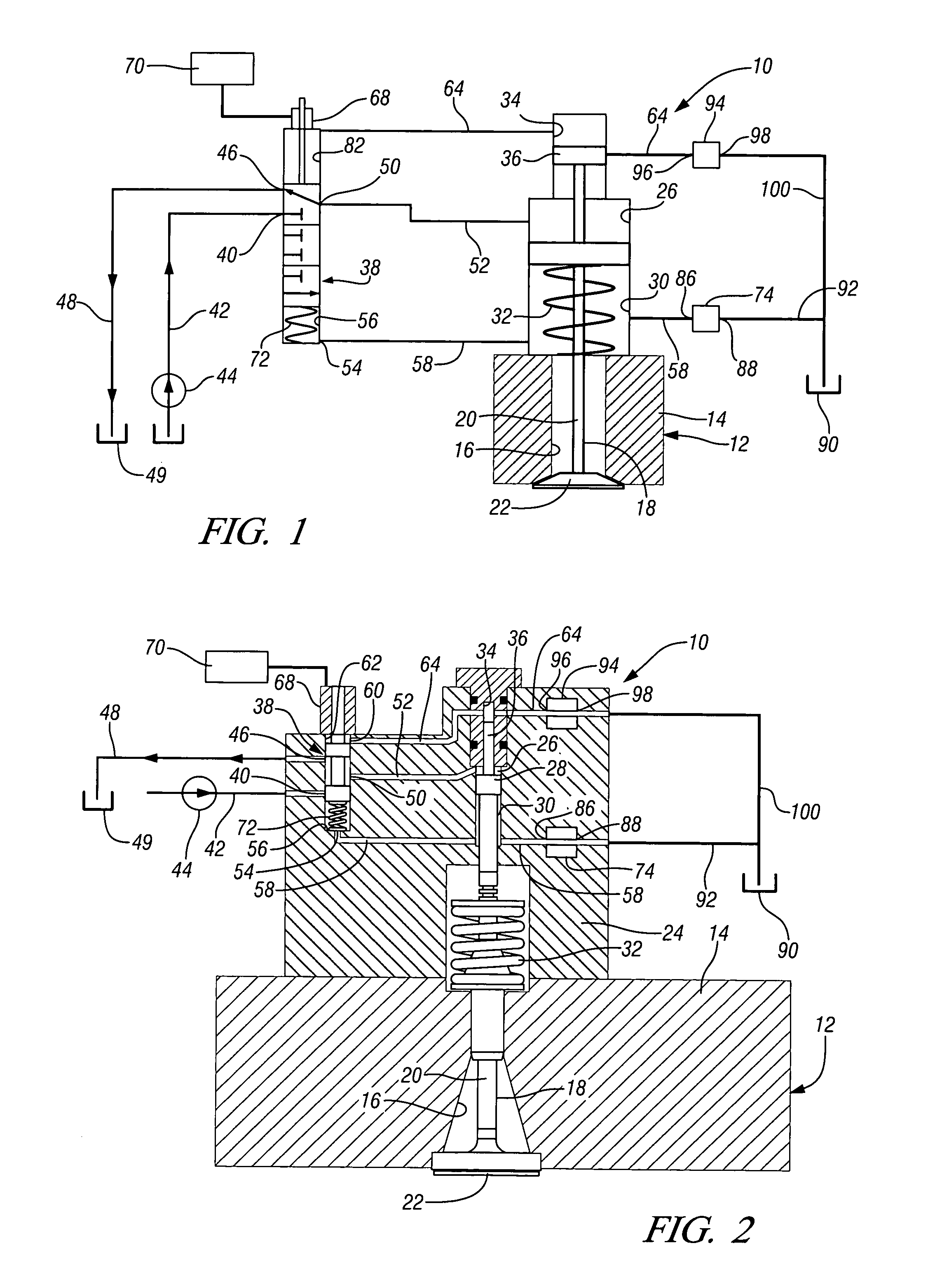
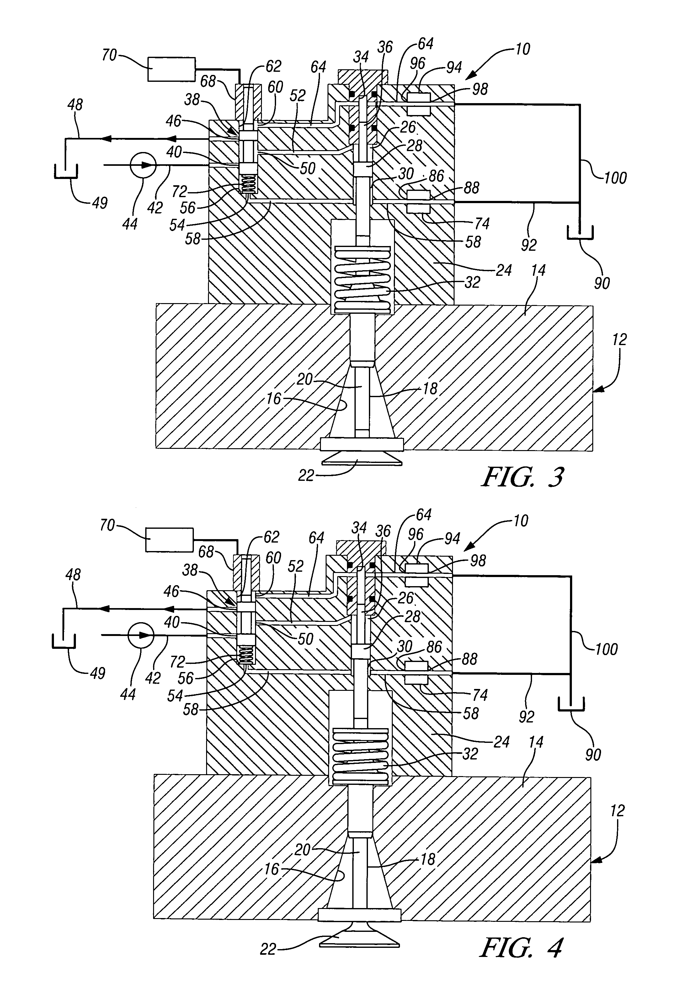
[0016]Referring first to FIGS. 1 and 2 of the drawings in detail, numeral 10 generally indicates an electrohydraulic valve actuator assembly mounted on a cylinder head 12 including at least one opening 16 in communication with an internal combustion chamber, not shown, of the engine. The cylinder head 12 also includes a movable engine valve 18 for each opening 16. The engine valve 18 has a valve stem 20 and a valve head 22 at one end of the valve stem. The engine valve 18 is movable between open and closed positions within its respective opening 16. It should be understood that the engine valve 18 may be either an intake or an exhaust valve.

[0017]The valve actuator assembly 10 further includes a valve housing 24 disposed adjacent the cylinder head 12. The valve housing 24 has a main or first fluid chamber 26 therein. A first piston 28 is connected to or in contact with the valve stem 20 of the engine valve 18. The piston 28 is disposed in the first fluid chamber 26 of the valve hous...


PUM


Abstract

A value actuator assembly for an engine includes a movable engine valve a movable spool valve and dual feedback channels with flow regulated by a pair of orifices. The valve actuator assembly also includes a driving channel interconnecting the spool valve and the engine valve. The feedback channels interconnecting the engine valve and the spool valve. First and second feedback channels communicate between the second and third fluid chambers and fourth and fifth fluid chambers of the spool valve. Orifices restrict fluid flow through the feedback channels as needed to actuate the spool valve and thereby improve valve controllability.

Description

CROSS-REFERENCE TO RELATED APPLICATIONS[0001]This application claims priority from U.S. Provisional Patent Application No. 60 / 587,321 filed Jul. 13, 2004.TECHNICAL FIELD[0002]This invention relates to engine valvetrains and, more particularly, to an electrohydraulic valve actuator assembly for an internal combustion engine.BACKGROUND OF THE INVENTION[0003]Valve actuator assemblies for camless valvetrains of internal combustion engines have been proposed in the art. Such actuators often result high energy consumption, low repeatability from cycle to cycle and cylinder to cylinder and high seating velocity-induced noise. Some valve actuator assemblies do not provide full capability of variable lift. They may also be of relatively high cost and have large packaging size.[0004]It is desirable to provide an engine valve actuator assembly that improves controllability. It is also desirable to provide a valve actuator assembly having increased flexibility and full capacity for variable lif...

Claims


Application Information

Patent Timeline
Patent Type & Authority Patents(United States)
IPC IPC(8): F01L9/10
CPCF01L9/02F01L2820/02F01L9/10
Inventor SUN, ZONGXUAN
Owner GM GLOBAL TECH OPERATIONS LLC
Why Eureka
Try Eureka