
Releasable side terminal battery cable connector clamp

Inactive Publication Date: 2006-04-18
FENELON MARGARET FENE +1
View PDF8 Cites 74 Cited by
  • Summary
  • Abstract
  • Description
  • Claims
  • Application Information

AI Technical Summary

Benefits of technology

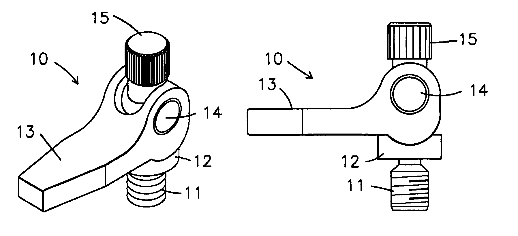
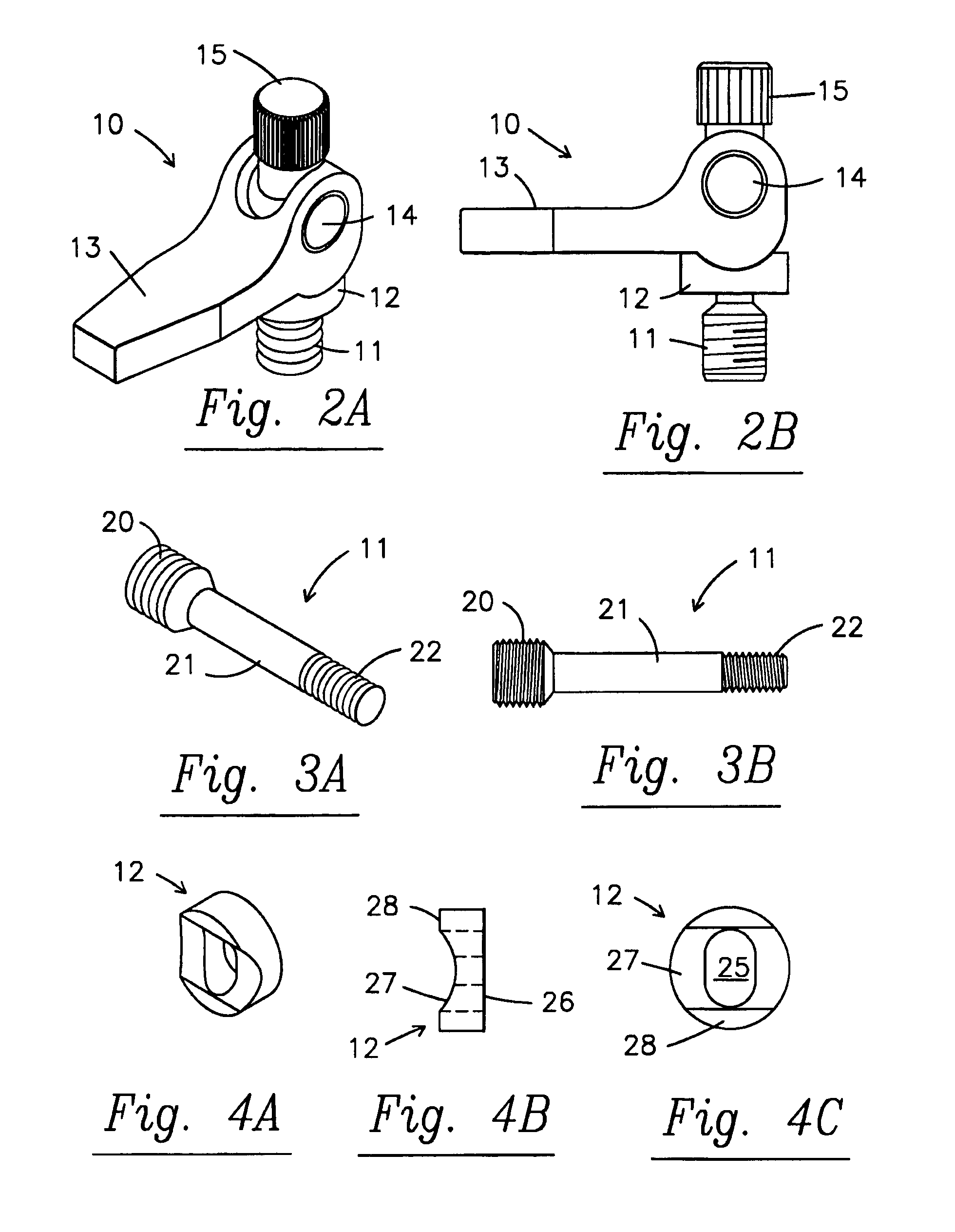
[0005]Instead of the standard bolt which passes through a battery cable terminal plate aperture and is tightened into a female aperture of the side-terminal, the side-terminal battery cable connector clamp of the invention utilizes a bolt with a clamping handle. The bolt with clamping handle (in open position) can be inserted through the aperture of the cable connector plate and loosely screwed into the female threaded side-terminal. The clamping handle includes a boss or camming structure that increases the clamping pressure based upon the angular rotation of the handle with respect to the bolt. By moving the clamping handle to its closed position, the connector plate is firmly engaged against the side-terminal conductive plate. When it is desired to remove the battery cable, the handle can be released to its open position and a substantial decrease in the clamping pressure of the bolt against the female threads of the side-terminal results. The handle rotates loosely in axial directions and does not turn the bolt on which it is mounted. In this fashion the handle can be axially oriented in any direction required in a restricted space. Preferably, the components of the side-terminal connection clamp assembly are made of non-corrosive and in some cases non-metallic materials such as stainless steel and glass filled nylon. In this fashion, preferably the entire operation of the invention is possible without need for using any additional tools.

Problems solved by technology

Due to cramped space in and around engine compartments where batteries are located, side-terminal connections may be necessary in some instances instead of top-post battery terminal connections.
During the course of the life of a battery, corrosion build up may occur and, indeed, side-terminal battery hardware is notorious for not wanting to turn.
Due to cramped conditions, it can be difficult to carry out these or other steps to loosen the side-terminal battery hardware.

Method used


Image

  • Releasable side terminal battery cable connector clamp
  • Releasable side terminal battery cable connector clamp
  • Releasable side terminal battery cable connector clamp

Examples


Embodiment Construction

[0023]A description of the preferred embodiment of the present invention will be best understood by referring to FIGS. 1–7 of the accompanying drawings wherein like numerals refer to like parts.

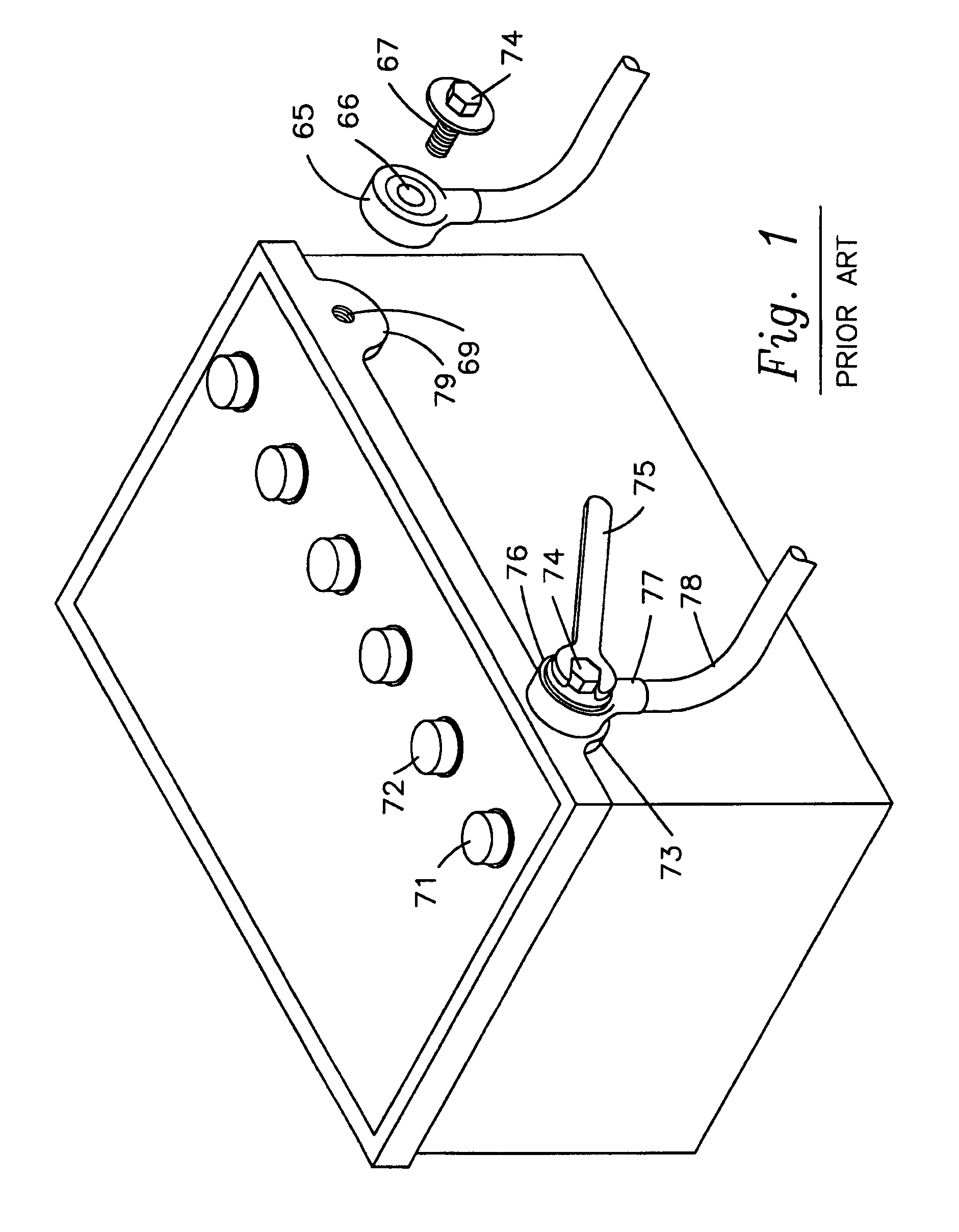
[0024]Referring first to FIG. 1, a typical 12-volt battery 70 is shown with positive top-post terminal 71 and negative top-post terminal 72. Battery 70 also has a positive side-terminal 73 and corresponding negative side-terminal 79. Prior art battery cable terminals 76 have a generally circular distal end 65 or connector plate with aperture 66 to receive bolt 74. Bolt 74 has male threads 67 that engage with female threads in the apertures 69 of side-terminals 73, 79. Battery cable terminals or connectors 76 have a proximal end 77 that receives and is secured to battery cable 78. Bolts 74 are fastened and unfastened with a wrench to firmly contact battery cable terminals 76 to side-terminals 73, 79 and establish an electrical connection. In use, side-terminal battery hardware is notorious for...


PUM


Abstract

A side terminal battery cable converter clamp is provided with a clamp shaft having a distal male threaded end adapted to mate with a female threaded side terminal, said clamp shaft carrying a cam seat, a cammed handle with pin, and a locknut, wherein the cammed handle is operable to frictionally engage and release the distal male threaded shaft end and female threaded side terminal.

Description

[0001]The present invention relates generally to battery cable clamps and more particularly to a battery cable clamp adapted for use on a side-terminal that may be easily fastened and released by hand.BACKGROUND ART[0002]It will be appreciated by those skilled in the art that most automobiles, motorized vehicles, and inboard boats are started by battery power and that the standard modern battery is a 12-volt battery having metal top-post terminals for the opposing polarities of the battery to which the terminals of battery cables are attached. In addition to, or in lieu of, top-post battery terminals, some 12-volt battery batteries have side-terminals. Side-terminals are conductive plates with female threaded apertures. The standard battery cable terminal or connector for a side-terminal has one end connected to the battery cable and the opposite end is a plate with an aperture. A bolt is received through the aperture of the connector plate into the female threaded side-terminal, an...

Claims


Application Information

Patent Timeline
IPC IPC(8): H01R4/30H01M50/541
CPCH01R11/282H01R4/5008
Inventor ORANGE, CHARLES M.ELLER, STEVE
Owner FENELON MARGARET FENE
Learn More