Water preclusion device for marine engine

a pre-venting device and engine technology, applied in marine propulsion, special-purpose vessels, vessel construction, etc., can solve the problems of limited springs, watercraft cannot accommodate high-rise-type exhaust systems, and watercraft exhaust pipes are not strong enough

Inactive Publication Date: 2006-04-18
YAMAHA MOTOR CO LTD
View PDF27 Cites 2 Cited by
  • Summary
  • Abstract
  • Description
  • Claims
  • Application Information

AI Technical Summary

Benefits of technology

[0009]One aspect of the present invention includes the realization that in-cylinder pressure of the engine of a watercraft can be used to operate a valve disposed in-line in the exhaust system, without relying on the positive pressure in main exhaust passage to open the valve. Thus, the exhaust system is not burdened with the additional back pressure for opening the valve, and the valve can include a stronger spring to bias it to a closed position.
[0012]In accordance with yet another aspect of the present invention, a method is provided for preventing water from flowing upstream in an exhaust system for a watercraft having an engine including an engine body defining at least one combustion chamber and a first exhaust conduit extending from the engine body to the atmosphere. The method comprises guiding pressure from the combustion chamber to a valve controller through a second conduit, and moving a valve to an open position with pressure in the second conduit. A watercraft comprising a hull defining the engine compartment, an engine positioned within the engine compartment, the engine comprising at least one cylinder including at least one cylinder port, an exhaust system including at least one exhaust valve configured to prevent the invasion of water into the engine, the cylinder port being communication with the exhaust valve, a pressure conduit communicating with the cylinder port for operating the exhaust valve while the engine is running
[0014]In accordance with yet another additional aspect of the present invention, a watercraft comprises a hull defining an engine compartment and an engine positioned within the engine compartment. The engine comprises at least one cylinder including at least one cylinder port. An exhaust system includes at least one exhaust valve configured to prevent the invasion of water into the engine. The cylinder port is in communication with the exhaust valve. A pressure conduit communicates with the cylinder port operating the exhaust valve while the engine is running. The pressure conduit incorporates an expansion chamber. The expansion chamber is configured to smooth pressure fluctuations in the pressure conduit.

Problems solved by technology

However, as soon as the engine stops, water can enter the exhaust pipe and cause damage.
However, such watercraft do not accommodate high-rise type exhaust systems.
However, such relatively weak springs are limited in that they do not provide sufficient pressure to completely seal the valve and thus allow water to enter under certain conditions.

Method used


Image

  • Water preclusion device for marine engine
  • Water preclusion device for marine engine
  • Water preclusion device for marine engine

Examples


Embodiment Construction

The Overall Construction

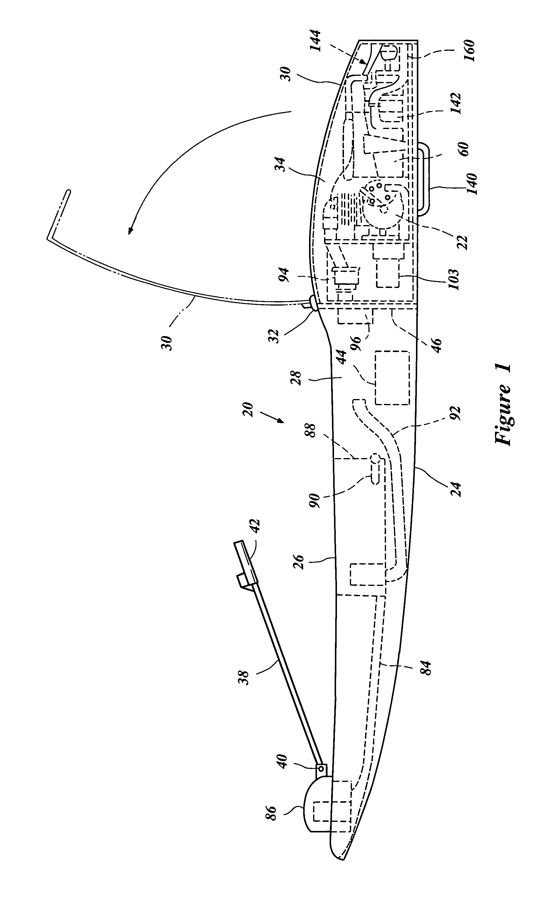
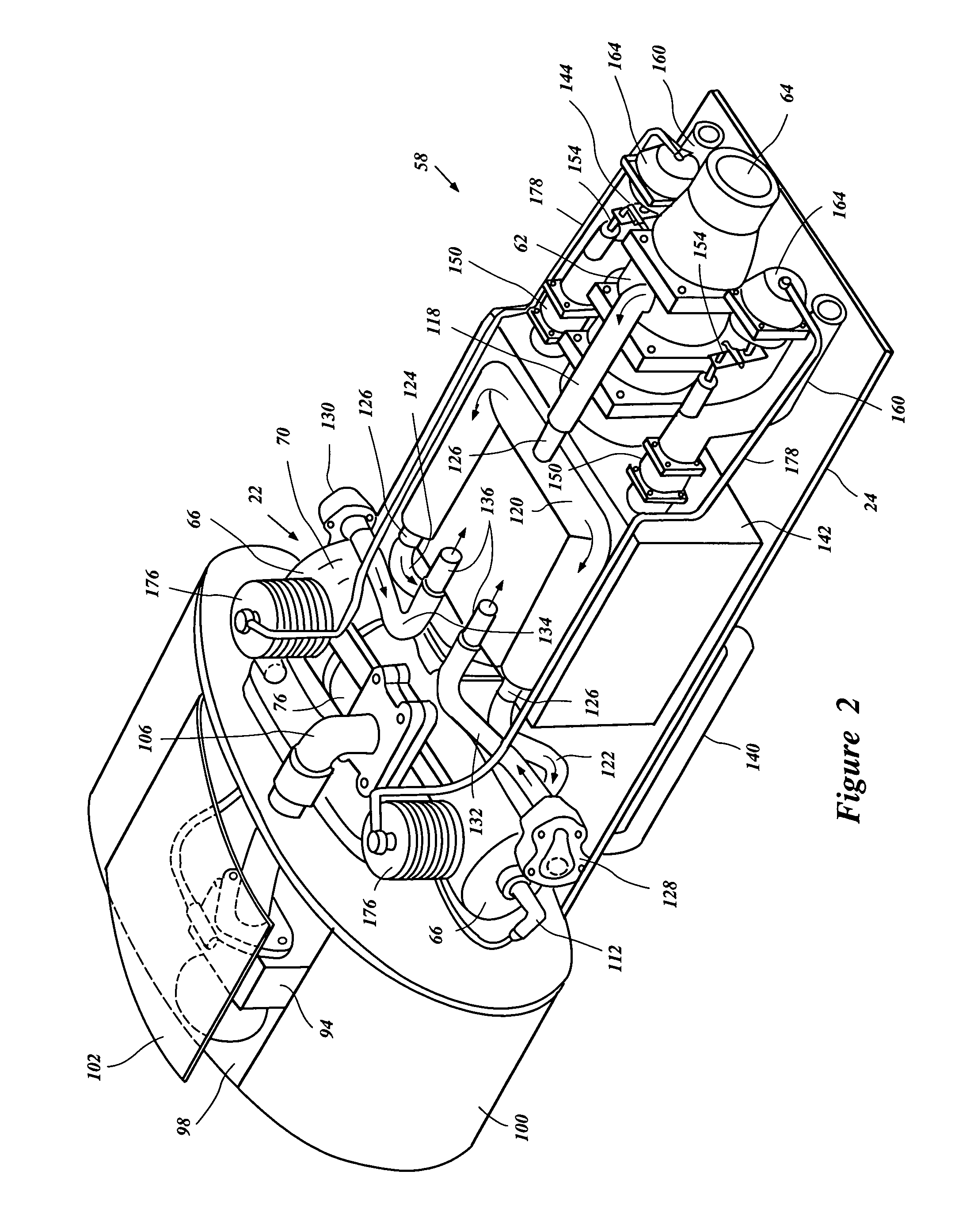
[0023]With reference to FIGS. 1 through 3, an overall configuration of a watercraft 20 and its engine 22 is described below. The watercraft 20 employs the internal combustion engine 22, which is configured in accordance with a preferred embodiment of the present invention. The described engine configuration has particular utility for use within the small watercraft, and thus, is described in the context of a personal watercraft. The engine configuration also can be applied to other types of vehicles, such as, for example, small jet boats, other water vehicles, and other land vehicles.

[0024]With reference initially to FIG. 1, the watercraft 20 includes a lower hull section 24 and an upper hull section or deck 26. The lower hull section 24 and the upper hull section 26 can be formed integrally or can be coupled together to define an internal cavity 28.

[0025]The internal cavity 28 can be divided into a plurality of separate compartments. In the illustrated embod...


PUM


Abstract

A water preclusion device for a watercraft with an internal combustion engine for inhibiting the intrusion of water upstream into an exhaust system. The water preclusion device includes a valve controlled by exhaust gas pressure.

Description

PRIORITY INFORMATION[0001]This application is based on and claims priority to Japanese Patent Application No. 2001-320078, filed Oct. 18, 2001 the entire contents of which is hereby expressly incorporated by reference.BACKGROUND OF THE INVENTION[0002]1. Field of the Invention[0003]The present invention relates generally to a water preclusion device for an engine, and more particularly to an improved water preclusion device using a valve controlled by in-cylinder pressure.[0004]2. Brief Description of Related Art[0005]Various watercraft engines with partially submerged exhaust systems which open to a body of water, typically incorporate a water preclusion device. When such an engine is running, the exhaust gases are discharged into the body of water through the exhaust pipe under a positive pressure. This positive pressure prohibits water from flowing into the engine. However, as soon as the engine stops, water can enter the exhaust pipe and cause damage.[0006]Many modern watercraft ...

Claims


Application Information

Patent Timeline
Patent Type & Authority Patents(United States)
IPC IPC(8): B63H21/34B63H11/08B63B35/73B63B35/79B63H21/32F01N13/08F01N13/12
CPCB63H21/32B63B35/731B63B34/10
Inventor ATSUSAWA, HIDENORI
Owner YAMAHA MOTOR CO LTD
Why Eureka
Try Eureka