Electronic endoscope apparatus

a technology of endoscope and endoscope, which is applied in the field of electronic endoscope apparatus, can solve the problems of affecting the operation or treatment of the adjustment process, the difficulty of adjusting the process, and the extremely high luminance level of the minute area of the screen, and achieve the effect of high luminance level

Inactive Publication Date: 2006-04-18
ASAHI KOGAKU KOGYO KK
View PDF5 Cites 24 Cited by
  • Summary
  • Abstract
  • Description
  • Claims
  • Application Information

AI Technical Summary

Benefits of technology

[0008]Therefore, an object of the present invention is to maintain the brightness of the subject properly regardless of the existence of minute areas with high luminance levels.

Problems solved by technology

However, because of a mucous membrane or an uneven surface of the observed portion, a luminance level of a minute area in the screen can become extremely high compared with the surrounding area.
This adjustment process is an obstacle to proper the operation or treatment.

Method used


Image

  • Electronic endoscope apparatus
  • Electronic endoscope apparatus
  • Electronic endoscope apparatus

Examples


first embodiment

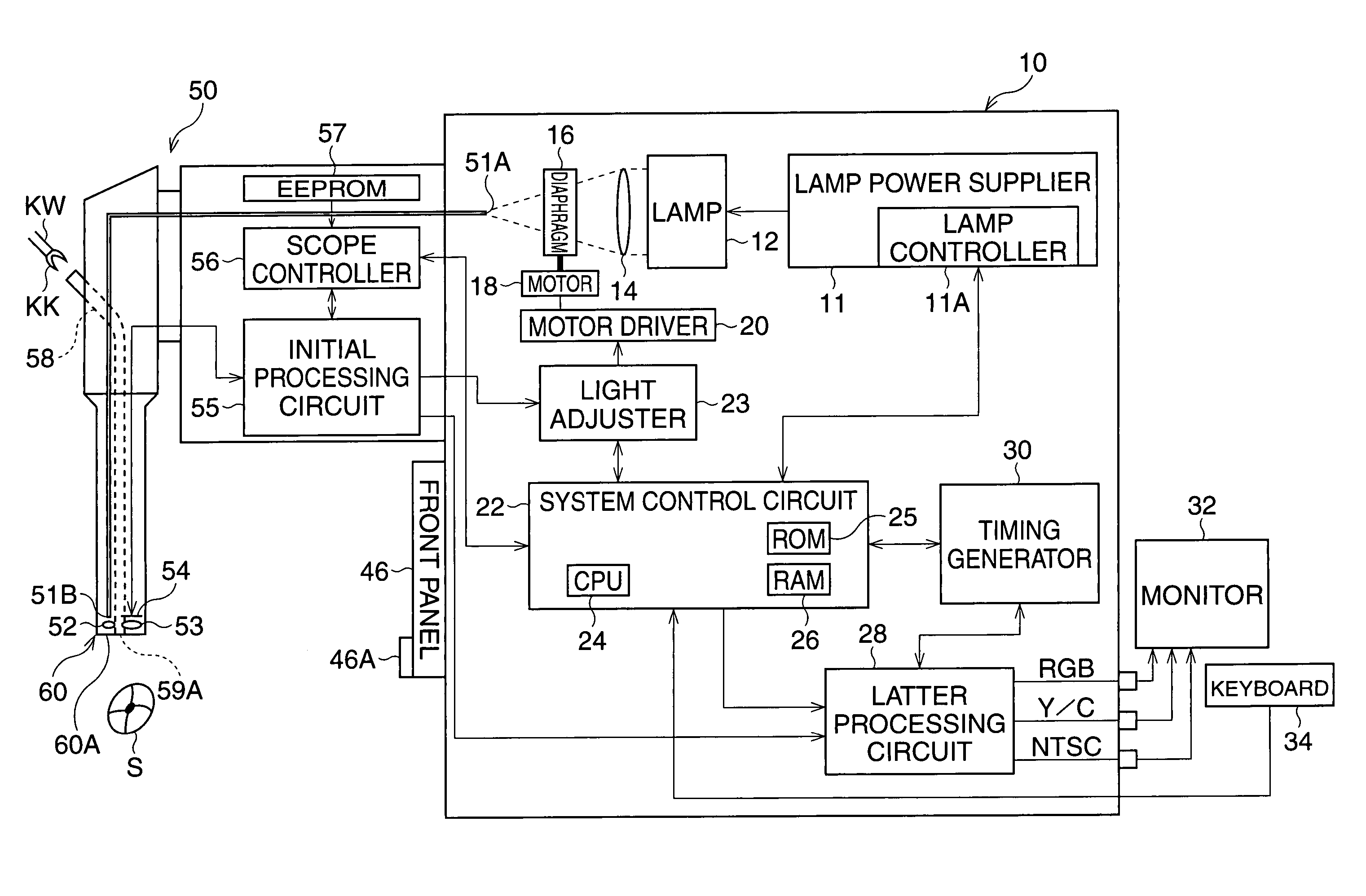
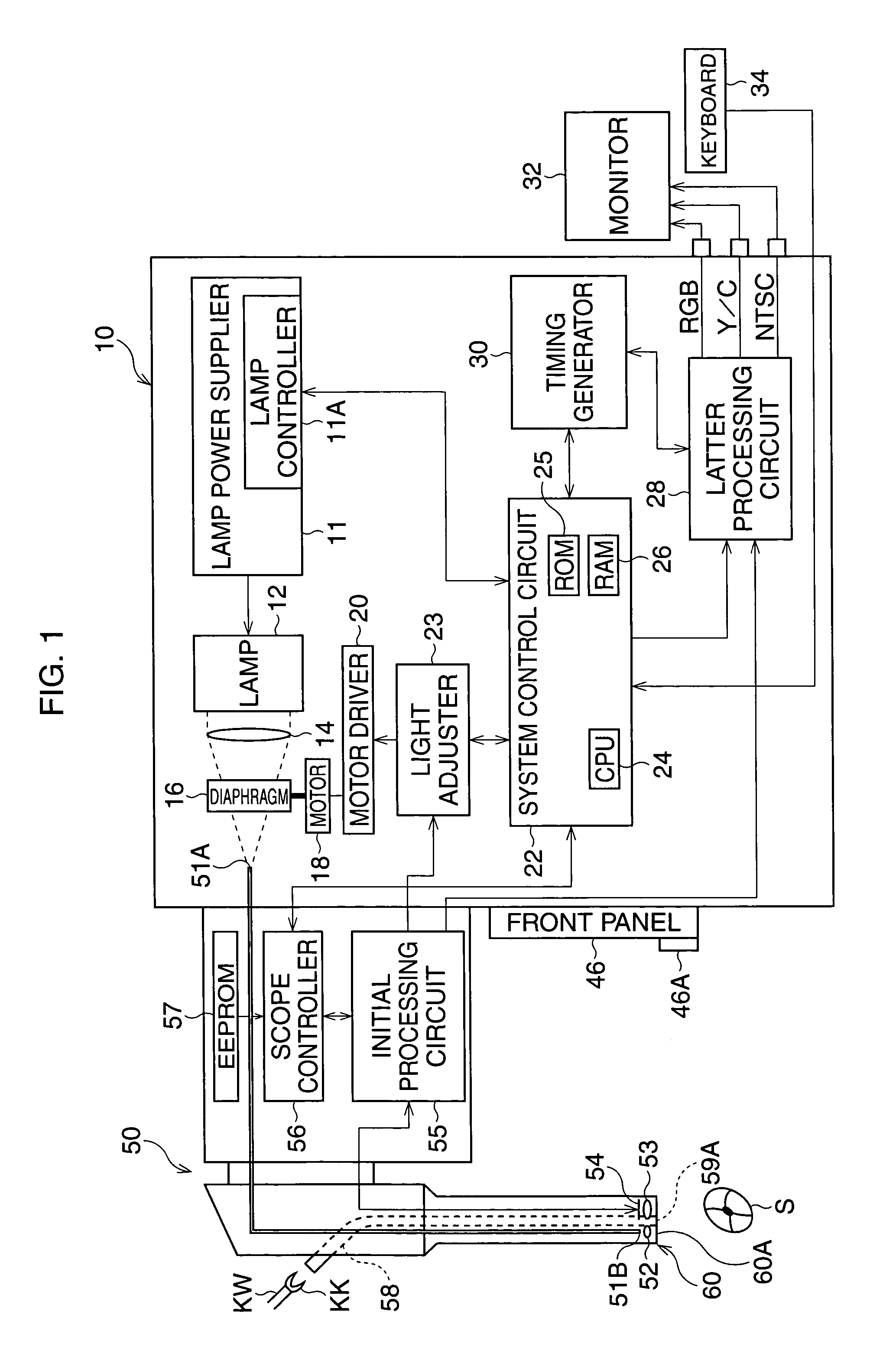
[0034]FIG. 1 is a block diagram of an electronic endoscope apparatus according to the

[0035]The electronic endoscope apparatus has a video-scope 50 with a CCD 54 and a video-processor 10. The video-scope 50 is detachably connected to the video-processor 10, and further a TV monitor 32 and a keyboard 34 are connected to the video-processor 10.

[0036]When a lamp switch provided on the video-processor 10 (not shown) is turned ON, electric power is supplied from a lamp power supplier 11 including a lamp controller 11A to a lamp 12, so that light is emitted from the lamp 12 and is directed toward an incident surface 51A of a fiber-optic bundle 51 via a collecting lens 14 and a diaphragm 16. The fiber-optic bundle 51, provided through the video-scope 50, directs the light toward the tip portion 60 of the video-scope 50.

[0037]The light passing through the fiber-optic bundle 51 exits from the end surface 51B of the fiber-optic bundle 51 and is emitted toward a subject S via a diffusion lens 5...

third embodiment

[0076]FIG. 7 is a block diagram of the

[0077]In the video-scope 50′, a tool sensor SE is provided at the forceps tube 58, and the tool sensor SE is connected to the scope controller 56. The tool sensor SE detects the insertion of the treatment tool KW, and outputs a detecting signal to the scope controller 56. The scope controller 56 feeds the control signal, informing of the use of the forceps KW, to the system control circuit 22, and the detecting signal is fed from the system control circuit 22 to the light adjuster 23. In the EEPROM 57, position data of the forceps outlet 59A on the tip surface 60A is stored in advance. When the video-scope 50′ is connected to the video-processor 10, the data including the position data of the forceps outlet 59A is fed to the system control circuit 22, and then the light adjuster 23.

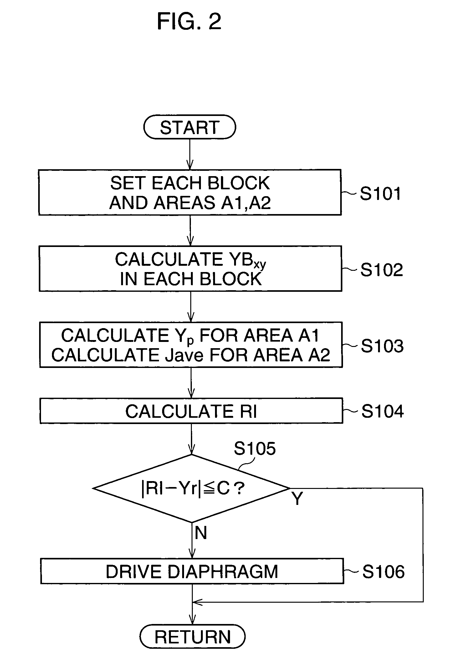
[0078]FIG. 8 is a flowchart of an automatic light-amount adjustment process according to the third embodiment. FIG. 9 is a view showing a metering-area of the observe...

second embodiment

[0079]In Step S301, it is determined whether the treatment tool KW is used. When it is determined that the treatment tool KW is not being used, that is the detecting signal is not input to the light adjuster 23, the process goes to Step S302. In Step S302, similarly to the second embodiment, the first peak metering-area “A′1”, the second peak metering-area “A′2”, and the average metering-area “A′3” are defined. After Step S302 is performed, the process goes to Step S304.

[0080]On the other hand, when it is determined that the treatment tool KW is being used, the process goes to Step S303. In Step S303, each block Bxy is set, and a first peak metering-area A″1, a second peak metering-area A″2, and the average metering-area A″3 are defined. In this case, the second peak metering-area A″2 is defined by removing an L-shaped area (hereinafter, called “forceps area”) KA from a rectangular-shaped form. The forceps area KA is defined in accordance with the position data stored in the EEPROM ...


PUM


Abstract

An electronic endoscope apparatus has a light source, a pixel luminance detector, a division setter, an average block luminance calculator, a peak-luminance determiner, a representative luminance calculator, and a brightness adjuster. The division setter divides the subject image into a plurality of blocks composed of given pixels. The average block luminance calculator calculates a plurality of average block-luminance-levels. The peak-luminance determiner compares the average block-luminance-levels with each other in order to determine a substantially maximum average block-luminance-level from the plurality of average block-luminance-levels as a peak luminance level. The representative luminance calculator calculates a representative luminance level indicating a brightness of the subject image. The brightness adjuster adjusts the brightness of the subject image in accordance with the representative luminance level.

Description

BACKGROUND OF THE INVENTION[0001]1. Field of the Invention[0002]The present invention relates to an electronic endoscope apparatus having a video-scope with an image sensor and a video-processor, and especially relates to a brightness adjustment process for a subject image displayed on a monitor.[0003]2. Description of the Related Art[0004]In an electronic endoscope apparatus, image-pixel signals are read from an image sensor provided at a tip portion of a video-scope, and a luminance level indicating the brightness of a displayed subject image is calculated from the image-pixel signals. Then,based on a difference between the luminance level and a reference level indicating a proper brightness of the subject image, the brightness of the subject image is adjusted so as to maintain a proper brightness. For example, the amount of light for illuminating the subject is adjusted by a diaphragm, whereas exposure time at the image sensor is adjusted by using an electronic shutter function.[...

Claims


Application Information

Patent Timeline
Patent Type & Authority Patents(United States)
IPC IPC(8): A61B1/06A61B1/018A61B1/04G02B23/24A61B1/05A61B1/07G02B23/26H04N7/18
CPCA61B1/018H04N7/183A61B1/05A61B1/0646A61B1/0655
Inventor KOBAYASHI, HIROYUKI
Owner ASAHI KOGAKU KOGYO KK
Why Eureka
Try Eureka