
OLED device having microcavity gamut subpixels and a within gamut subpixel

a technology of organic electroluminescent and microcavity, which is applied in the direction of incadescent envelope/vessel, discharge tube luminescnet screen, discharge tube/lamp details, etc., can solve the problem of no power saving for displaying any portion of the digital image, red, green and blue subpixel efficiency does not improve in this design, and achieves the effect of improving efficiency and life and reducing cos

Active Publication Date: 2006-04-18
GLOBAL OLED TECH
View PDF26 Cites 136 Cited by
  • Summary
  • Abstract
  • Description
  • Claims
  • Application Information

AI Technical Summary

Benefits of technology

[0006]It is an object of the present invention to make use of an OLED display device that has pixels having gamut subpixels and within gamut subpixels that can substantially improve the efficiency of the gamut subpixels.
[0010]By constructing a gamut subpixels with a microcavity structure the present invention provides improved efficiency and lifetime. It is a further advantage that such a device can be constructed using a common OLED organic layers for all subpixels which does not require precision patterning to from the subpixels. It is a further advantage that such a device can be constructed without the need for color filter elements, which thereby lowers cost.

Problems solved by technology

This results in improved power consumption relative to an RGB constructed of similar OLED materials.
However, the red, green, and blue subpixels do not improved in efficiency in this design.
Therefore, no power savings are achieved for displaying any portion of the digital image content that is pure red, pure blue, or pure green in color such as, for example, icons and toolbars commonly used in many personal digital assistant (PDA), cell phone, or digital camera applications.
It is known that OLED devices degrade, or become less efficient, more quickly as current density is increased.
For an RGBW display, this may result in content which is pure red, pure green, or pure blue, and appearing frequently such as, for example, icons and toolbars causing image burn-in quicker than in an equivalent RGB display and therefore overall device lifetime is reduced.

Method used


Image

  • OLED device having microcavity gamut subpixels and a within gamut subpixel
  • OLED device having microcavity gamut subpixels and a within gamut subpixel
  • OLED device having microcavity gamut subpixels and a within gamut subpixel

Examples


Embodiment Construction

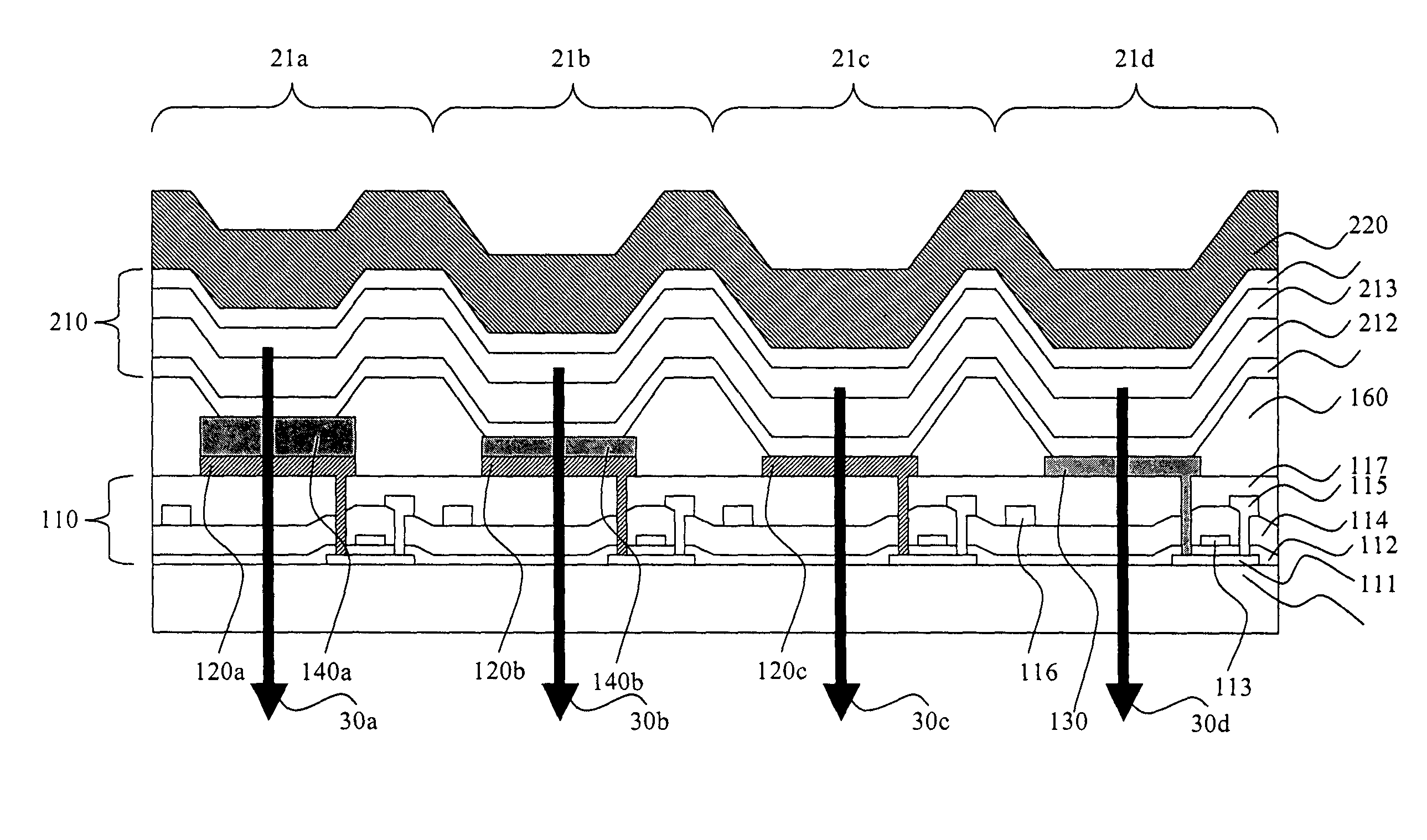
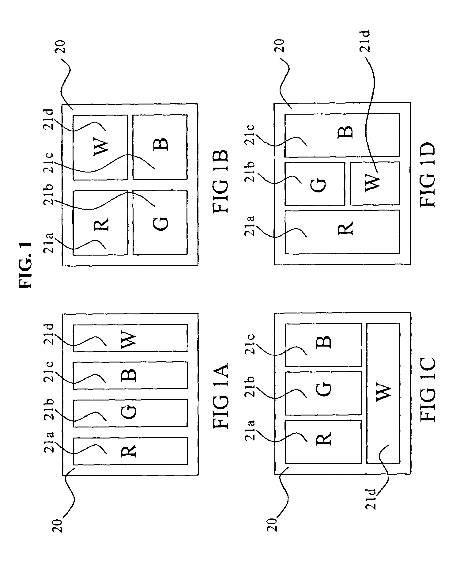
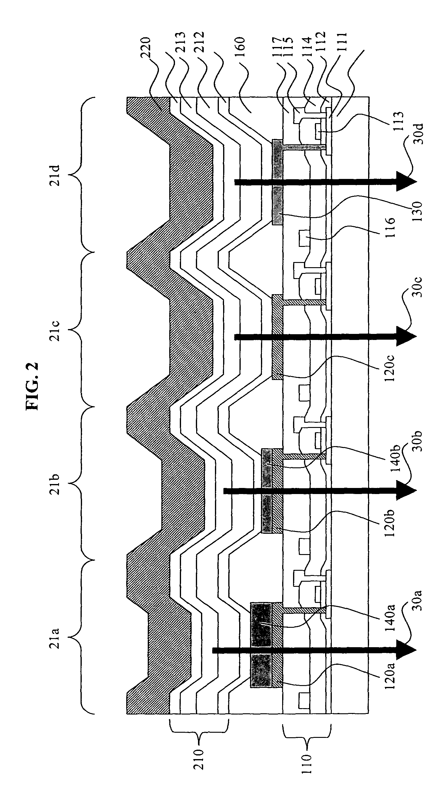
[0015]RGBW displays are one example of a type of display that utilizes within-gamut emission to improve power consumption. Such display devices are capable of displaying color images through the use of pixels having at least four different color subpixels. At least three of the subpixels are gamut subpixels that emit different colors, which define the color gamut of the display. For example, gamut subpixels might emit light that is either Red, Green, or Blue in color. By illuminating two or more of the gamut subpixels to varying intensities, other colors can be generated. These new colors are within-gamut colors. Such a display device also has at least one additional subpixel that is a within-gamut subpixel, which emits a within-gamut color light such as white. The term white is used in the present invention to indicate any light emission which is perceived as approximately white to a viewer. These within-gamut subpixels generally are more efficient than the gamut subpixels. FIG. 1 ...


PUM


Abstract

An OLED device including an array of light emitting pixels, each pixel including subpixels having organic layers including at least one emissive layer that produces light and spaced electrodes, and wherein there are at least three gamut subpixels that produce colors which define a color gamut and at least one subpixel that produces light within the color gamut produced by the gamut subpixels; and wherein at least one of the gamut subpixels includes a reflector and a semitransparent reflector which function to form a microcavity.

Description

CROSS-REFERENCE TO RELATED APPLICATIONS[0001]Reference is made to commonly-assigned U.S. Publication No. 2004 / 0140757, published Jul. 22, 2004, entitled “Microcavity OLED Devices” by Tyan et al, U.S. Publication No. 2004 / 0149984, published Aug. 5, 2004, entitled “Color OLED Display with Improved Emission” by Tyan et al, U.S. Pat. No. 6,861,800, issued Mar. 1, 2005, entitled “Tuned Microcavity OLED Display” by Tyan et al, U.S. patent application Ser. No. 10 / 412,534, filed Apr. 11, 2003, entitled “A Color OLED Display With Improved Power Efficiency” by Arnold et al and U.S. Pat. No. 6,919,681 issued Jul. 19, 2005, entitled “A Color OLED Display With Improved Power Efficiency” by Cok et al, the disclosures of which are incorporated herein.FIELD OF INVENTION[0002]This invention relates to microcavity organic electroluminescent (EL) devices.BACKGROUND OF THE INVENTION[0003]Full color organic electroluminescent (EL), also known as organic light-emitting devices or (OLED), have been recent...

Claims


Application Information

Patent Timeline
Patent Type & Authority Patents(United States)
IPC IPC(8): H01J1/62H01J63/04H05B33/00H01L27/15H01L27/32H01L51/52
CPCH01L27/3213H01L51/5265H01L27/3244H10K59/351H10K59/12H10K59/876H05B33/22H01J1/00H01J63/04H01L27/15H10K50/852
Inventor WINTERS, DUSTINTYAN, YUAN-SHENGVAN SLYKE, STEVEN A.COK, RONALD S.ARNOLD, ANDREW D.
Owner GLOBAL OLED TECH
Learn More