Liquid crystal display

a technology of liquid crystal display and leds, applied in the field of liquid crystal display, can solve the problems of inability to ensure the brightness necessary for satisfactory display, inability to ensure the light-emitting time, etc., and achieve the effect of increasing the light-emitting time ratio

Inactive Publication Date: 2006-04-18
JAPAN DISPLAY CENT INC
View PDF6 Cites 29 Cited by
  • Summary
  • Abstract
  • Description
  • Claims
  • Application Information

AI Technical Summary

Benefits of technology

[0015]The present invention has been developed for obviating the above-mentioned problems and an object of the present invention is to provide a liquid...

Problems solved by technology

Consequently, the light-emitting time Th of the LEDs necessary for sufficient brightness canno...

Method used


Image

  • Liquid crystal display
  • Liquid crystal display
  • Liquid crystal display

Examples


embodiment 1

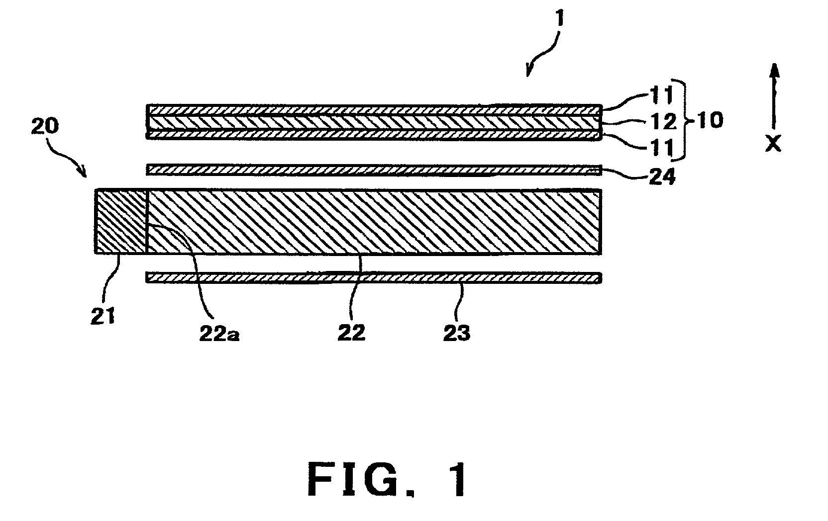
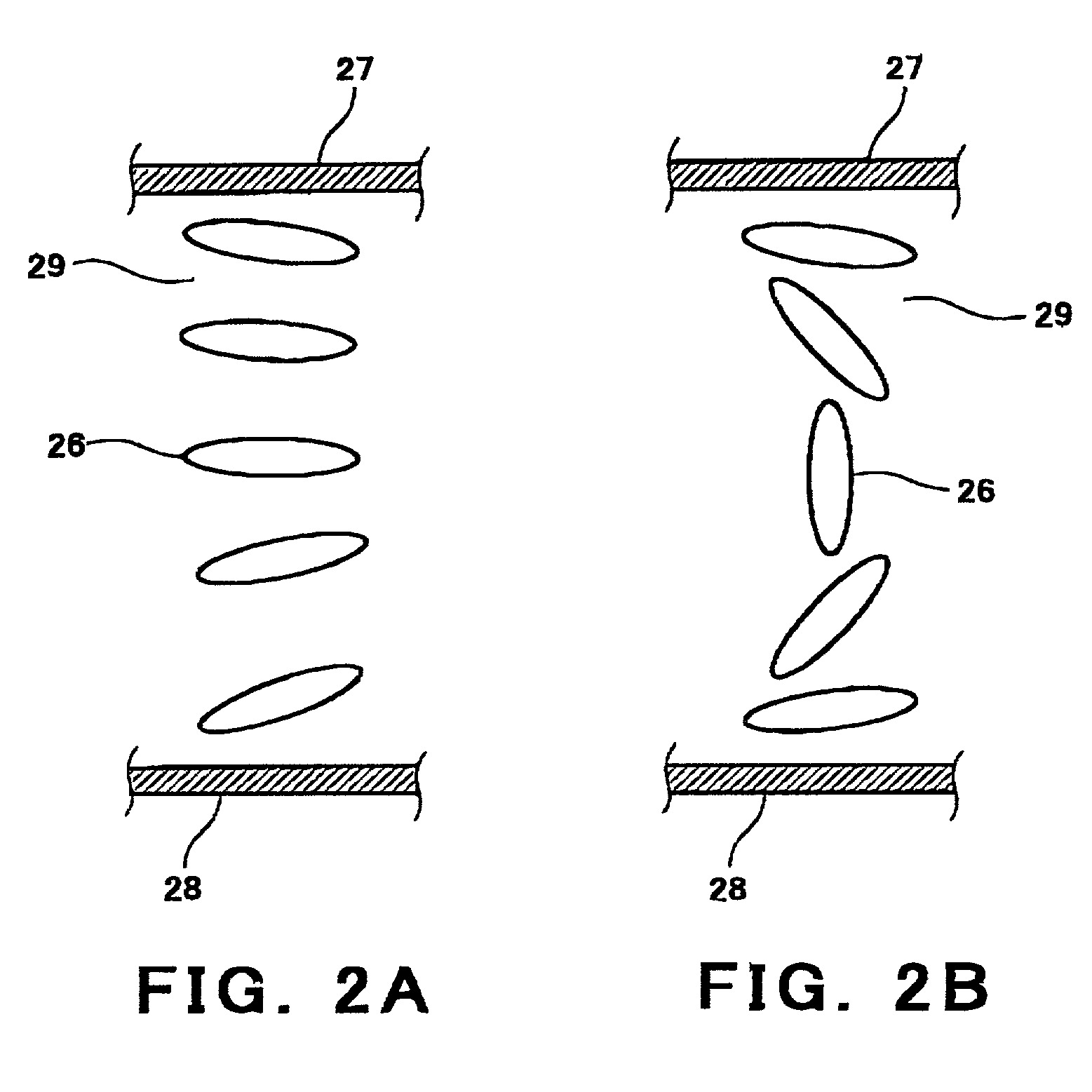
[0099]FIG. 1 is a cross-sectional view schematically showing a constitution of a liquid crystal display according to a first embodiment. FIGS. 2A, 2B are cross-sectional views schematically showing alignment state of liquid crystal filled into a liquid crystal layer included in the liquid crystal display. In these Figures, for the sake of convenience, a direction indicated by an arrow X indicates an upper side of a liquid crystal display 1.

[0100]Referring now to FIG. 1, the liquid crystal display 1 comprises a liquid crystal display panel 10 structured such that polarizers 11 are bonded to both sides of a liquid crystal cell 12. The liquid crystal cell 12 comprises two substrates, i.e., an upper substrate 27 and a lower substrate 28 disposed opposite to each other as spaced by a spacer (not shown) between them. A liquid crystal layer 29 contains liquid crystal 26 filled into a gap between the upper substrate 27 and the lower substrate 28.

[0101]The liquid crystal display panel 10 so ...

embodiment 2

[0136]A second embodiment illustrates a liquid crystal display in which the non-video signal write period of the first embodiment is divided into two periods and different non-video signal voltages are applied in these periods. In brief, the liquid crystal display is adapted to perform writing of two different non-video signals in the 1st writing. The constitution of the liquid crystal display of this embodiment is identical to that of the first embodiment, and as such, a detailed description is omitted.

[0137]FIGS. 11A–11D are timing charts showing an example of display's drive mechanism of the liquid crystal display according to the second embodiment of the present invention. FIG. 11A shows timings at which the scan signals are output to the gate lines of the liquid crystal display panel. FIG. 11B shows waveforms of the signals output to a source line 32 of the liquid crystal display panel, FIG. 11C shows change in transmittance in pixels on respective rows of the liquid crystal di...

embodiment 3

[0145]In the first embodiment, one frame period is divided into three sub-frame periods. A third embodiment illustrates a liquid crystal display in which one frame period is divided into four sub-frame periods. The constitution of the liquid crystal display of this embodiment is identical to that of the first embodiment, and as such, a description is omitted.

[0146]FIGS. 12A–12C are timing charts showing an example of display's drive mechanism of a liquid crystal display according to a third embodiment of the present invention. FIG. 12A shows timings at which the scan signals are output to the gate lines of the liquid crystal display panel, FIG. 12B shows waveforms of the signals output to a source line 32 of the liquid crystal display panel, FIG. 12C shows change in transmittance in pixels on respective rows of the liquid crystal display panel, and FIG. 12D shows light-emitting time of LEDs of a backlight. The signal waveforms of FIG. 12B are illustrated for easy understanding of th...


PUM


Abstract

Disclosed is a liquid crystal display capable of ensuring brightness necessary for achieving satisfactory display by increasing ratio of light-emitting time to one frame period. A liquid crystal display is adapted to have a period (non-video signal write period) required for writing non-video signals different from video signals onto all the pixels before a video signal write period. In the non-video signal write period, the non-video signals are written onto the respective pixels, thereby starting response of the liquid crystal before the start of the video signal write period. In the non-video signal write period, a backlight is turned off, and thereby image degradation is prevented even when the non-video signals are written onto the respective pixels.

Description

FIELD OF THE INVENTION[0001]The present invention relates to a liquid crystal display. More particularly, the present invention relates to a liquid crystal display capable of ensuring sufficient light-emitting time in one frame period.DESCRIPTION OF THE RELATED ART[0002]In recent years, active matrix type liquid crystal displays (hereinafter simply expressed as liquid crystal displays) have been widely used as displays for use in notebook or desktop computers.[0003]The conventional liquid crystal displays generally employ a color filter method in which white light is adapted to travel through color filters of three primary colors, i.e., red, green, and blue provided for respective pixels, thereby conducting color display. In the liquid crystal display using such color filter method, because display is conducted for each set of three pixels, i.e., red, green, and blue pixels as described above, its resolution is as high as ⅓ of the number of pixels included in a liquid crystal displa...

Claims


Application Information

Patent Timeline
IPC IPC(8): G09G3/36G02F1/133G09G3/34
CPCG09G3/342G09G3/3648G09G3/3413G09G2310/0224G09G2310/0235G09G2320/064G09G2310/0248G09G2310/061G09G2310/08G09G2320/0266G09G2310/024G02F1/133
Inventor SATO, ICHIROKUMAGAWA, KATSUHIKOYAMAKITA, HIROYUKIKOMORI, KAZUNORI
Owner JAPAN DISPLAY CENT INC
Why Eureka
Try Eureka