Center frequency adjustment for a notch filter

a center frequency adjustment and notch filter technology, applied in the field of data storage devices, can solve the problems of reducing servo control performance and lowering and achieve the effect of reducing the effect of resonance frequency and reducing the effect of servo control performan

Inactive Publication Date: 2006-04-18
IBM CORP
View PDF19 Cites 10 Cited by
  • Summary
  • Abstract
  • Description
  • Claims
  • Application Information

AI Technical Summary

Benefits of technology

[0010]The present invention is designed to solve the foregoing technical problems, and it is an object of the invention to reduce effects of a resonance frequency of an actuator or the like without a reduction in servo control performance.

Problems solved by technology

However, the increased cutoff frequency band width of the notch filter results in an increase of a phase delay at the servo band frequency present at a frequency lower than the center frequency set in the notch filter, and the phase margin of the servo loop is thus reduced lowering servo control performance.

Method used


Image

  • Center frequency adjustment for a notch filter
  • Center frequency adjustment for a notch filter
  • Center frequency adjustment for a notch filter

Examples


first embodiment

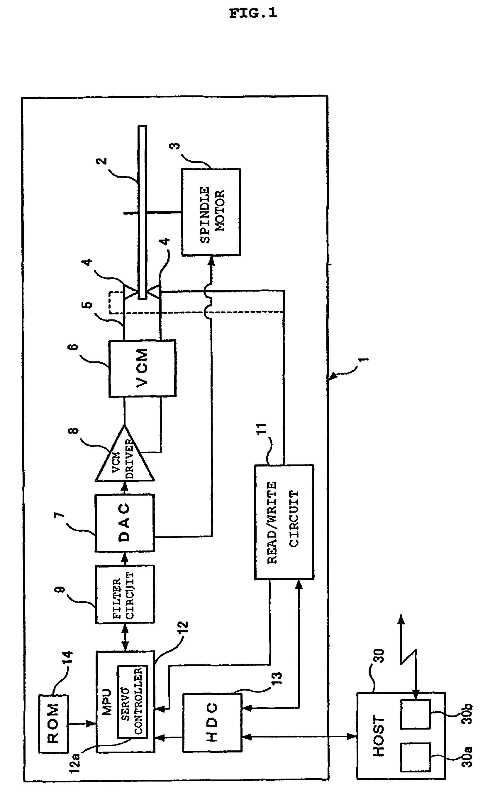
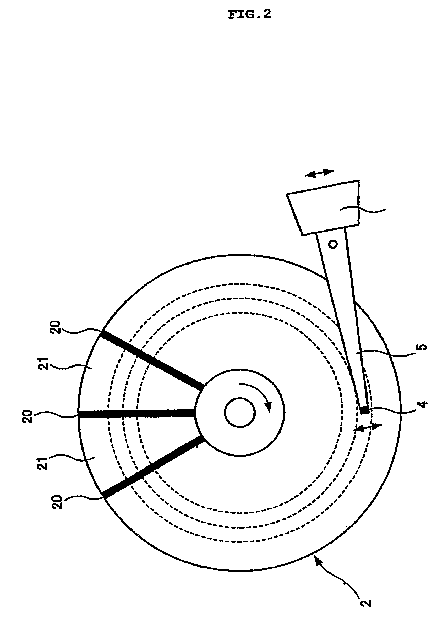
[0035]FIG. 1 is a block diagram showing main sections of a hard disk drive 1 according to a first embodiment. The hard disk drive 1 has a magnetic disk 2, a spindle motor 3, a magnetic head 4, an actuator 5, a voice coil motor (VCM) 6, a digital / analog converter (DAC) 7, a VCM driver 8, a filter circuit 9, a read / write circuit 11, a micro processing unit (MPU) 12, a hard disk controller (HDC) 13, and a read only memory (ROM) 14. The hard disk drive 1 is connected through the HDC 13 to a host computer (HOST) 30. The hard disk drive 1 is a storing / reproducing device in which the magnetic head 4 seeks on the magnetic disk 2 rotary-driven by the spindle motor 3 and stays on a predetermined track (target track) to write data on the magnetic disk 2 or read data written on the magnetic disk 2. A single or a plurality of magnetic disks 2 are loaded as necessary. An example of a single magnetic disk 2 is shown in FIG. 1.

[0036]While the hard disk drive 1 is operating, the magnetic disk 2 is r...

second embodiment

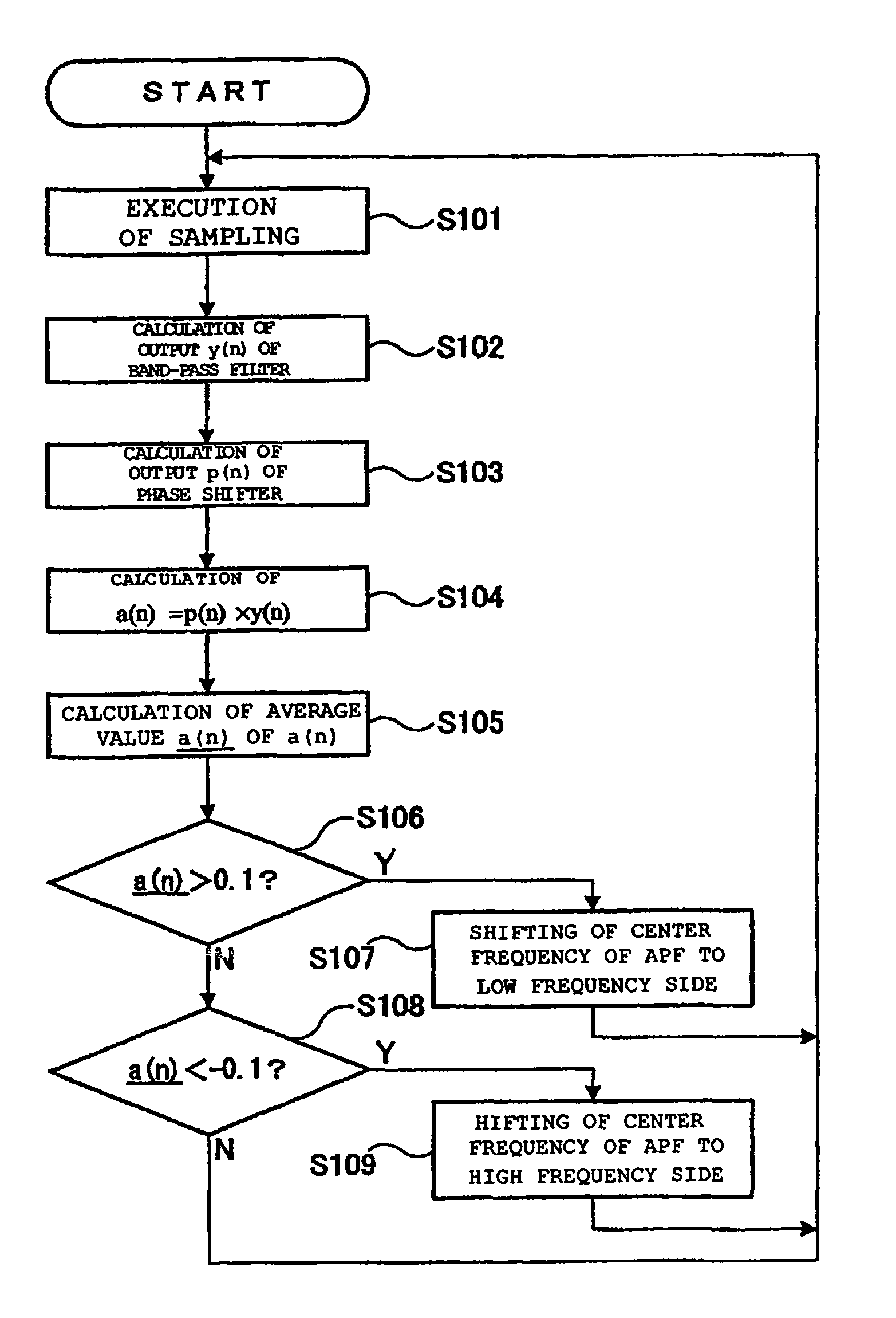
[0074]FIG. 11 shows a filter circuit 9 according to a second embodiment. This embodiment is roughly similar to the first embodiment, but different in that a notch filter and a band-pass filter are individually formed instead of realizing the notch filter and the band-pass filter by all pass filters (APF) and adders. Portions of the embodiment similar to those of the first embodiment are denoted by the same reference numerals as those of the first embodiment, and detailed description will be omitted.

[0075]The filter circuit 9 according to the embodiment is provided with a notch filter (NF) circuit 40 having an NF 41, a band-pass filter (BPF) 51, an all pass filter (APF) 52, a multiplier 53, an averaging unit 54, and a BPF circuit 50 having a RAM 55. Then, an output of the NF circuit 40 is connected to a DAC 7 (see FIG. 1), and an output of the BPF circuit 50 is fed back to a servo controller 12a.

[0076]According to the embodiment, detection is made by the BPF circuit 50 as to how muc...


PUM

PropertyMeasurementUnit
resonance frequencyaaaaaaaaaa
center frequencyaaaaaaaaaa
frequencyaaaaaaaaaa

Abstract

Disclosed is a data storage device, a servo control method, and a program to reduce effects of a resonance frequency of an actuator or the like without reduction in servo control performance. A band-pass filter comprising a first all pass filter (APF) and a second adder, a second APF, and a multiplier are used to detect how much a current resonance frequency of the actuator deviates from a set value of a center frequency of the first APF, and based on a result of the detection, the center frequency of the first APF is properly adjusted. The adjustment of the center frequency of first APF enables a center frequency of a notch filter comprising the first APF and a first adder to be automatically approximated to a current resonance frequency of the actuator.

Description

BACKGROUND OF THE INVENTION[0001]1. Field of the Invention[0002]The present invention relates to data storage devices and, in particular, to suppression of mechanical resonance, and more particularly to suppression of mechanical resonance by using a notch filter.[0003]2. Description of the Related Art[0004]A hard disk drive widely used as an external storage device for a computer device is provided with a magnetic head for reading user data stored on a magnetic disk, or for writing user data on the magnetic disk. The magnetic head is attached to an actuator mechanism oscillated by a voice coil motor (VCM). When reading or writing of the user data is executed by the magnetic head, the actuator mechanism is driven to move and position the magnetic head on a specific track (target track). The magnetic head is controlled to move to a predetermined position based on servo information stored on the magnetic disk.[0005]In the magnetic disk such as a hard disk, a plurality of data tracks ar...

Claims


Application Information

Patent Timeline
Patent Type & Authority Patents(United States)
IPC IPC(8): G11B5/596G11B21/10G11B5/00G11B5/012G11B5/55
CPCG11B5/59622G11B5/5526G11B2005/001G11B7/08505
Inventor KISAKA, MASASHI
Owner IBM CORP
Why Eureka
Try Eureka