
Starter for electricmagnetic converter, and timepiece

Inactive Publication Date: 2006-04-18
SEIKO EPSON CORP
View PDF29 Cites 18 Cited by
  • Summary
  • Abstract
  • Description
  • Claims
  • Application Information

AI Technical Summary

Benefits of technology

[0035]With the invention having those features, the startup member is employed which has the engaging portion capable of mechanically engaging with the rotation target gear of the mechanical energy transmitting means. As compared with a conventional starter utilizing a frictional force, therefore, a mechanical rotating force can be more efficiently applied to the rotation target gear with higher stability. The above first object is thus achieved.
[0083]With the timepiece having those features, because of including the starter for the electromagnetic converter which is used as a motor, when the electromagnetic converter is stopped, for example, during the hand setting operation and the timepiece is then returned from the hand setting operation, the electromagnetic converter can be quickly started up at a predetermined rotational speed with stability. Accordingly, an error in indication of the time can be made very small and the timepiece can be operated with high accuracy.

Problems solved by technology

However, the above electronically controlled mechanical watch has problems as follows.
However, because the power generator and the associated driving mechanism have their own inertia, it takes a time for the power generator to transit from a stopped state to an ordinary driving (rotating) state due to the inertia.
As a result, the amount of power produced by the power generator is small in an initial stage of the startup of the power generator, and charging takes a time until the terminal voltage of the capacitor reaches the IC driving start voltage.
Stated otherwise, a problem has been experienced in that a certain period of time is needed from the start of driving of the power generator to the start of operation of the IC, and precise time control cannot be made during that period of time.
In the above invention, however, the driving lever applies a mechanical rotating force to the gear with a frictional force, thus resulting in a problem that it is difficult to efficiently apply the rotating force with stability.
Such a problem is not limited to a power generator, but occurs likewise when a mechanical rotating force is applied to a motor gear with a frictional force using a driving lever.
In other words, the above problem is in common to any cases where a driving lever is provided to impose a rotating force on a gear of mechanical energy transmitting means, such as a rotor or a train wheel for driving the rotor, in electromagnetic converters including power generators or motors.
This has raised a problem that a difficulty in setting of the rotating force makes it hard to apply a stable rotating force.
In practice, if a return spring is too strong, a sufficient rotating torque cannot be applied because the spring causes the abutment lever to depart away from the gear before the startup.
Conversely, if the return spring is too weak, the abutment lever is brought into contact with the gear upon an impact or the like.
Another problem in the case of applying a mechanical rotating force to a gear resides in efficiency.
It is very difficult to output energy at such a low efficiency of not more than 5% with stability.
This has raised a problem of difficulty in rotating the gear with stability.
Moreover, another problem of the above-cited invention has been encountered in that it is difficult to correctly set the time with high accuracy because the rotational speed of the sped-up rotor does not become stable unless the rotating force applied to the gear of the wheel train is controlled by the driving lever with high accuracy.
This has raised a problem that the correct time cannot be set even with compensation using a preset value, thus resulting in a difficulty in setting the time right with high accuracy.
This necessity has raised still another problem that, although such a parameter can be easily managed up to accuracy enough for ordinary uses, the parameter is difficult to manage at accuracy higher than such a level.

Method used


Image

  • Starter for electricmagnetic converter, and timepiece
  • Starter for electricmagnetic converter, and timepiece
  • Starter for electricmagnetic converter, and timepiece

Examples


first embodiment

[0118]An embodiment of the present invention will be described below in connection with the drawings.

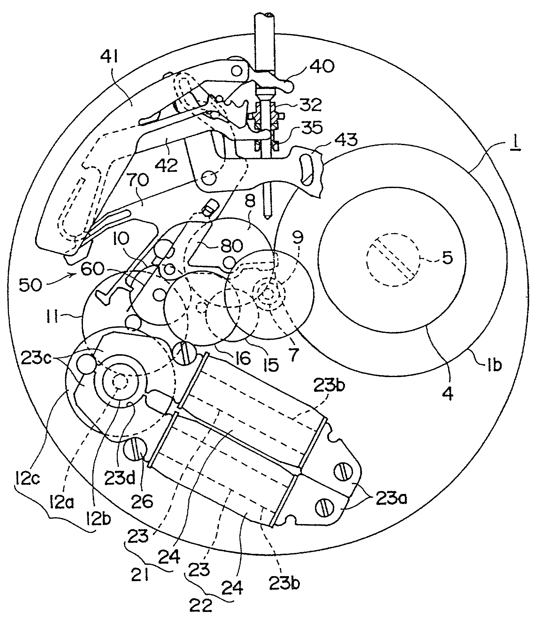
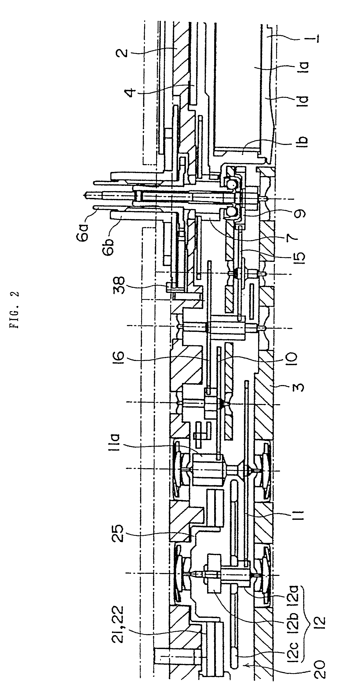
[0119]FIG. 1 is a plan view showing principal part of an electronically controlled mechanical watch according to a first embodiment of the present invention, and FIGS. 2 and 3 are sectional views of the principal part.

[0120]The electronically controlled mechanical watch includes a movement barrel 1 comprising a mainspring 1a, a barrel wheel gear 1b, a barrel arbor, and a barrel cover 1d. The mainspring 1a has an outer end fixed to the barrel wheel gear 1b and an inner end fixed to the barrel arbor. The barrel arbor is inserted through a barrel axle fixed to a main plate 2 and is fixed by a ratchet wheel screw 5 for rotation together with a ratchet wheel 4.

[0121]The ratchet wheel 4 is meshed with a click (not shown) so that it is allowed to rotate counterclockwise, but checked from rotating clockwise. A manner of rotating the ratchet wheel 4 clockwise to wind up the mainspring 1a is s...

second embodiment

[0179]Next, a second embodiment of the present invention will be described. Note that, in the following embodiments, the same or similar components as those in the above embodiment are denoted by the same symbols and a description thereof is omitted or abridged.

[0180]FIG. 12 is a plan view showing principal part of an electronically controlled mechanical watch according to a second embodiment of the present invention, and FIGS. 13 and 14 are sectional views of the principal part.

[0181]The electronically controlled mechanical watch includes a movement barrel 1 comprising a mainspring 1a serving as a mechanical energy source, a barrel wheel gear 1b, a barrel arbor, and a barrel cover 1d. The mainspring 1a has an outer end fixed to the barrel wheel gear 1b and an inner end fixed to the barrel arbor. The barrel arbor is inserted through a barrel axle fixed to a main plate 2 and is fixed by a ratchet wheel screw 5 for rotation together with a ratchet wheel 4.

[0182]The ratchet wheel 4 is ...

third embodiment

[0237]Next, a third embodiment of the present invention will be described. Note that, in this embodiment, the same or similar components as those in the above first embodiment are denoted by the same symbols and a description thereof is omitted or abridged.

[0238]In the above first embodiment, the latch portion 73 and the startup-spring biasing portion 74 of the reset lever 70 are formed as integral parts of a one-piece member and the relative positional relationship between them is not changed. In this embodiment, as shown in FIGS. 23 and 24, a slit is formed in the reset lever 70 between the latch portion 73 engaging with the 6th pinion 11a and the startup-spring biasing portion 74 for biasing the startup spring 60 so that the latch portion 73 and the startup-spring biasing portion 74 are constructed as separate pieces and the relative positional relationship between them is changeable.

[0239]Further, in the above first embodiment, the startup spring 60 is fixed to the main plate 2 ...


PUM


Abstract

A starter which applies a mechanical rotating force to a rotor of an electromagnetic converter, such as a power generator, for startup of the rotor. The starter includes a startup spring (60) having an engaging portion (63) engageable with a 6th pinion (11a) of a wheel train coupled to the power generator. In interlock with the operation of pulling out a crown, a reset lever (70) is operated to bias the startup spring for engagement with the 6th pinion. Thereafter, the startup spring is released from the biased state in interlock with the operation of pushing in the crown. The startup spring is returned to the original position due to its own spring force, whereupon a mechanical rotating force is applied to the pinion. Since the rotating force can be set by a resilient force of only the startup spring, a stable rotating force is applied to the rotor (12).

Description

TECHNICAL FIELD[0001]The present invention relates to a starter for an electromagnetic converter such as a power generator or a motor, and a timepiece, such as a wristwatch, including the starter.BACKGROUND ART[0002]Japanese Unexamined Patent Application Publication No. 8-5758 discloses one of known electronically controlled mechanical watches wherein hands fixed to a wheel train are precisely driven to indicate the time of day right by converting mechanical energy produced upon unwinding of a mainspring into electrical energy with a power generator, operating a rotation controller with the electrical energy, and then controlling a current value flowing through a coil of the power generator.[0003]In operation of the above watch, the electrical energy produced from the power generator is once supplied to a smoothing capacitor, and the rotation controller is driven with power from the capacitor. However, because an AC electromotive force is always inputted to the capacitor in synch wi...

Claims


Application Information

Patent Timeline
IPC IPC(8): G04B1/00G04B27/04G04C10/00
CPCG04C10/00G04B27/04
Inventor NAGASAKA, EIICHITAKAHASHI, OSAMU
Owner SEIKO EPSON CORP
Learn More