Dynamic power control in integrated circuits

a technology of integrated circuits and power control, applied in the direction of liquid/fluent solid measurement, instruments, sustainable buildings, etc., can solve the problems of static power consumption, e.g., longer operating times possible without increasing the physical size of the device, and low power consumption, so as to simplify the structure and test the system, and save power functions. the effect of time and simplifying the structur

Active Publication Date: 2006-04-18
NOKIA TECHNOLOGLES OY
View PDF11 Cites 23 Cited by
  • Summary
  • Abstract
  • Description
  • Claims
  • Application Information

AI Technical Summary

Benefits of technology

[0012]It is an aim of the present invention to provide a new solution for dynamic power control to minimize the power consumption in integrated circuits, particularly in application specific integrated circuits, in such a way that the above-presented problems of prior art are avoided by the invention.
[0017]The invention makes it possible to save power in a more effective and aggressive way than in solutions of prior art; that is, the hardware units can be kept as long as possible in the actual powered-down mode or in the wake up mode of the invention. By means of the invention, however, the system response times remain known, because after the activation of the second status signal, said hardware unit is always ready for operation after a given delay with a known duration of time. In difference to prior art, this also makes it possible to execute functions which require precise execution in real time, in a faultless manner, because as said delay is now known, the delay can be taken into account in the programming of the operations of the system.
[0018]In an advantageous embodiment of the invention, the entry of the hardware unit in the powered-down mode will affect not only the clock frequency but also the operating voltage to be supplied to said hardware unit. This will further reduce the power consumption in the powered-down mode.
[0020]By means of the invention, it is possible, for example, to provide effective power saving functions on an ASIC circuit without reducing the response times of the functions of said circuit. By means of the invention, there is no need to continuously maintain information about the operating state of the system in a separate state machine or the like, whose implementation, as known from prior art, requires a memory and also other resources of the system. Consequently, the invention significantly simplifies the structure and testing of the system to be implemented, for example, on an ASIC circuit, compared with solutions of prior art.
[0021]In the solution of the invention, the operation of single hardware units remains fully independent of each other (asynchronic), and the hardware units are always activated in the operating mode according to the need; therefore, this will significantly facilitate the programming of the functions included in the system. Also, when the functions of the system are being determined by programming, it is now easy to take into account the known delay times for the transfer of the hardware units from the wake up mode to the operating mode.

Problems solved by technology

Low power consumption makes e.g. longer operating times possible without increasing the physical size of the devices.
In this context, static power consumption refers to the power consumption of the circuit in a situation, in which the circuit is in the idle state, not executing any actual functions but with the operating voltage turned on.
The static power consumption of ASIC circuits is largely determined by the processing technique used in the manufacture of the circuits, and thus it cannot be significantly influenced by the design of the functionality of the circuits.
In circuit designing, determining the functions to be included in the ASIC circuit being designed, it is, however, possible to significantly influence the dynamic power consumption of the circuit.
However, the operating voltage and the clock frequency of the circuit can also be changed during the use, wherein it is further possible to affect the dynamic power consumption of the circuit.
However, state machines or the like, implemented by software, have the drawback that they must be allocated resources, such as a memory, on the integrated circuit.
The use of state machines will also require that the processor unit belonging to the system is kept active, which increases the power consumption.
Furthermore, the software processing and storage of powered-down modes allowed for the states and different hardware units in a system will significantly increase delays upon turning the powered-down mode on and off.
This will cause problems particularly in such solutions in which schedules are designed to be critical so that the too late activation of a hardware unit from the powered-down mode to the operating mode, or vice versa, will interfere with other processes or hardware units in the system by causing delays or actual malfunctions.
The above-presented dynamic powered-down solutions of prior art have proven to be unsatisfactory, particularly in solutions requiring very aggressive power saving but still precisely predictable system response times. When using solutions of prior art, particularly in more complex systems comprising several hardware units, the delay times for “energizing” the system to operation from the powered-down mode to a standby mode are very difficult to predict under changing conditions, wherein, to be on the safe side, the system must be energized slightly in advance, before the moment when the system should be ready for operation at the latest.
Thus, when the system is ready for operation but it does not yet execute any actual function, it unnecessarily consumes energy.

Method used


Image

  • Dynamic power control in integrated circuits
  • Dynamic power control in integrated circuits
  • Dynamic power control in integrated circuits

Examples


Embodiment Construction

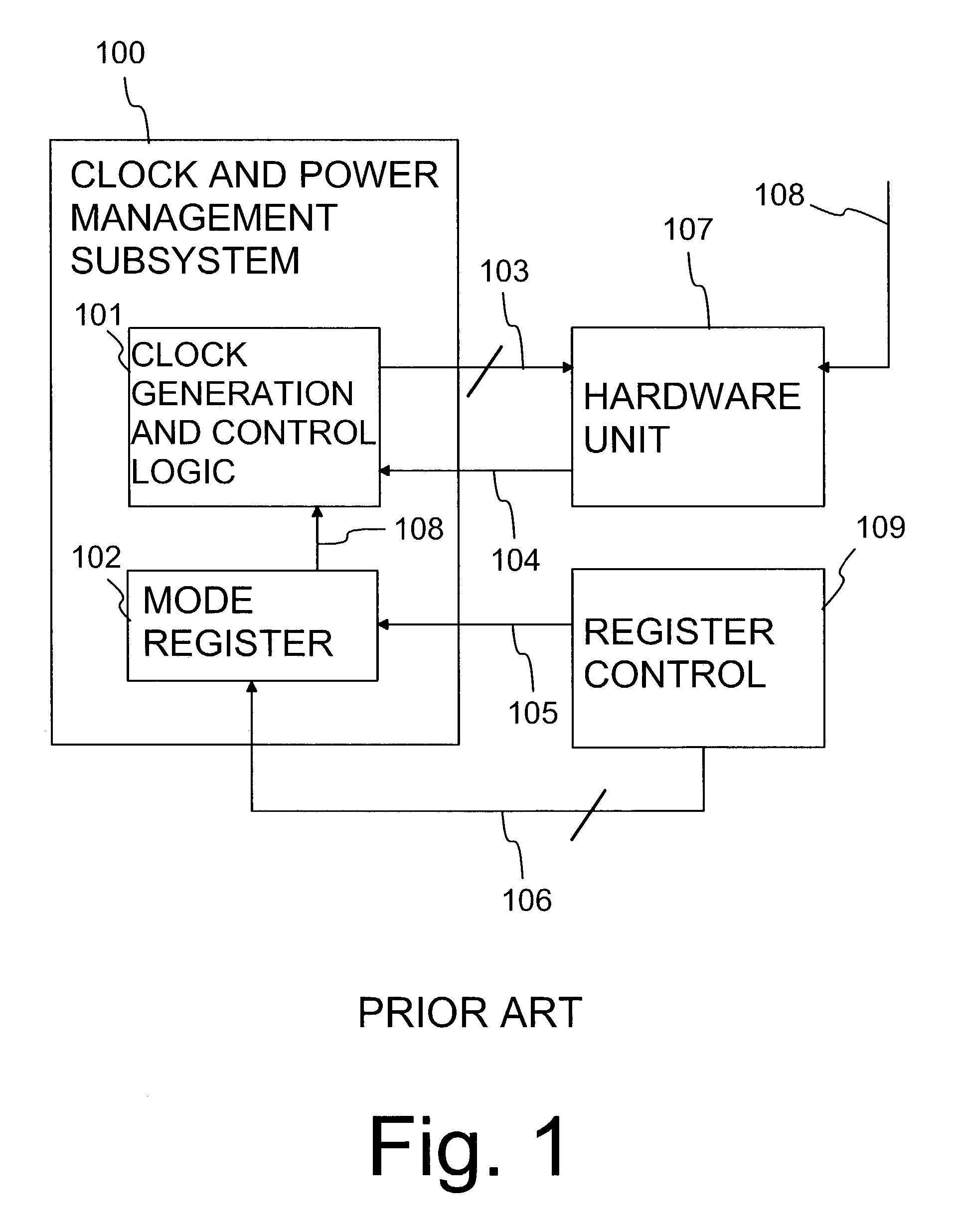
[0027]FIG. 1 has already been discussed above in the description of prior art.

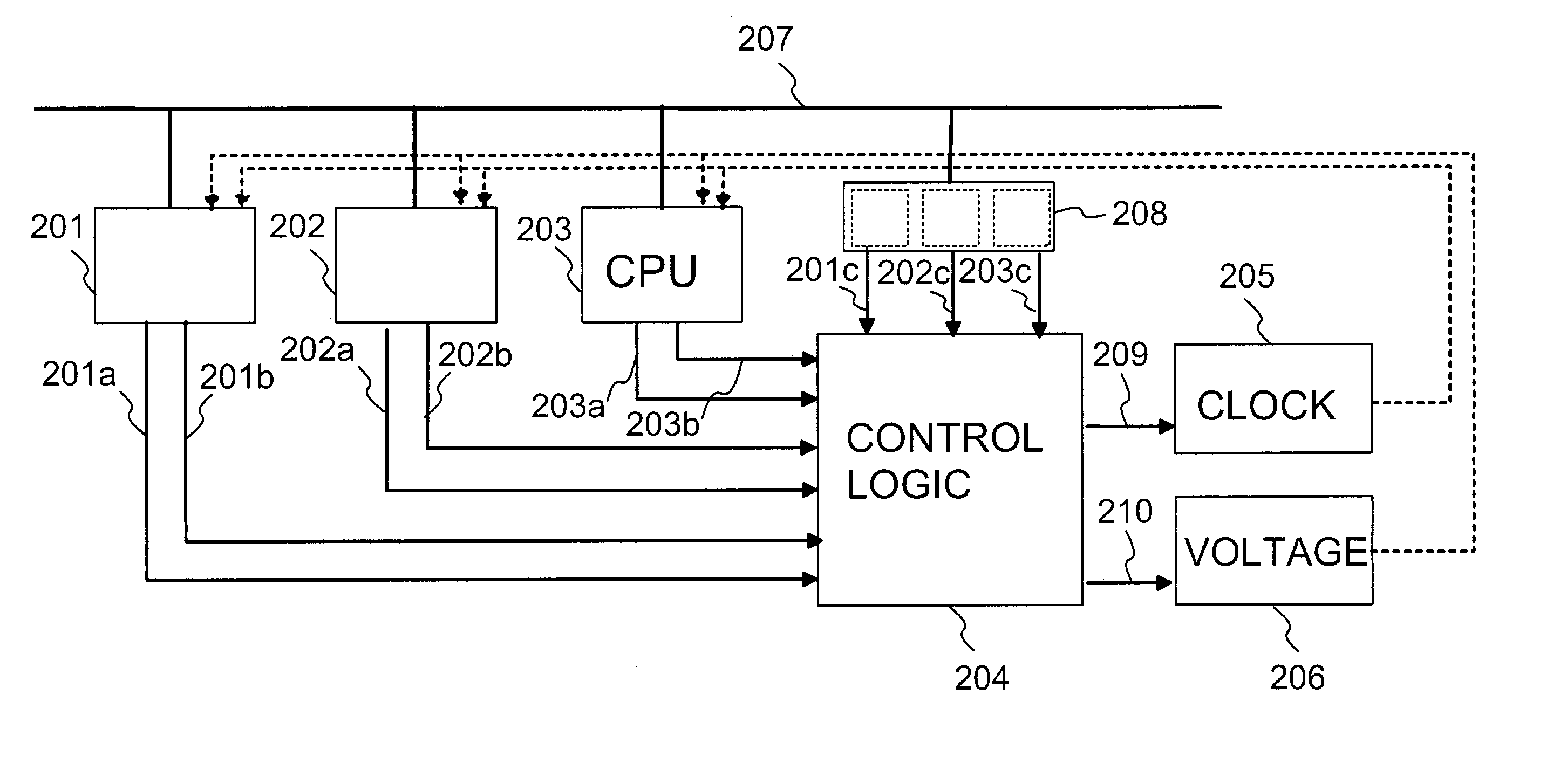
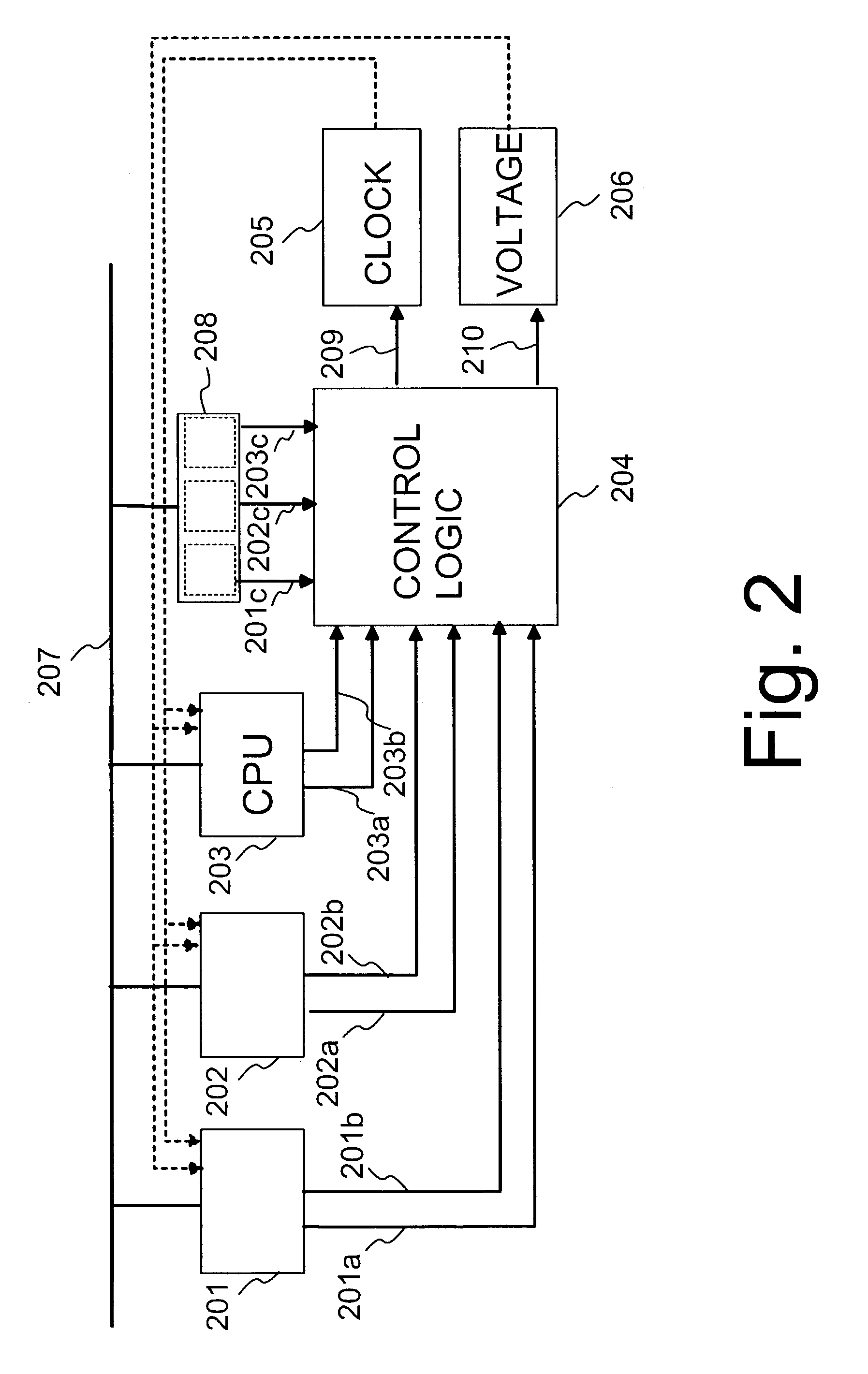
[0028]FIG. 2 shows a system which is preferably implemented on a single ASIC circuit and comprises several hardware units 201–203, a power control logic 204, as well as clock frequency and operating voltage control units 205, 206. The hardware units 201–203 as well as the power control logic 204 are connected to communicate via a bus 207.

[0029]According to the invention, each single hardware unit 201–203 can generate a first status signal 201a–203a and a second status signal 201b–203b, which status signals are transferred to the power control logic 204.

[0030]Furthermore, requirement signals 201c–203c are transferred to the power control logic 204, transmitting information from a power control mode register 208 to the power control logic 204. The power control mode register 208 contains information for each hardware unit 201–203 about the clock frequency and / or operating voltage to be generated to the singl...


PUM


Abstract

A method and device is disclosed for implementing dynamic power control in an electronic system implemented on an integrated circuit, which electronic system comprises at least one or several hardware units (201, 202, 203), a hardware based power control logic (204) substantially implemented with logic circuits, as well as a programmable power control mode register (208) containing information about powered-down modes defined for said one or more hardware units. To transfer a single hardware unit (201, 202, 203) from the powered-down mode to the operational mode, the hardware unit transmits to the power control logic (204) a first level sensitive status signal (201a, 202a, 203a) for transferring the hardware unit from the powered-down mode to the wake up mode, and further a second level sensitive status signal (201b, 202b, 203b) for transferring the hardware unit from the wake up mode to the actual operating mode.

Description

CROSS REFERENCE TO RELATED APPLICATIONS[0001]This application claims priority under 35 USC §119(a) to Finnish Patent Application No. 20012535 filed on Dec. 20, 2001.FIELD OF THE INVENTION[0002]The present invention relates to a method for dynamic power control to minimize the power consumption in integrated circuits, particularly in application specific integrated circuits (ASIC). The invention also relates to a power control system implementing such a method.BACKGROUND OF THE INVENTION[0003]Integrated circuits (abbreviated IC) are widely used in the implementation of various electronic devices. In a number of applications, for example in mobile stations or other battery-operated compact and portable devices, the power consumption of integrated circuits contained in the devices is a very essential factor to be considered in the design and implementation of the devices. Low power consumption makes e.g. longer operating times possible without increasing the physical size of the device...

Claims


Application Information

Patent Timeline
Patent Type & Authority Patents(United States)
IPC IPC(8): G06F1/00G06F1/32
CPCG06F1/3203G06F1/3228G06F1/324G06F1/3296G06F1/3287Y02B60/1285Y02B60/1217Y02B60/1282Y02D10/00
Inventor KOLINUMMI, PASIVEHVILAINEN, JUHANI
Owner NOKIA TECHNOLOGLES OY
Why Eureka
Try Eureka