Device and method for adjusting the torque transmitted by a friction clutch

a technology of friction clutch and torque transmission, which is applied in the direction of electric digital data processing, toothed gearings, instruments, etc., can solve the problems of affecting the torque transmission relationship between the torque of the electric motor and the torque transmitted, and affecting the accuracy of setting

Inactive Publication Date: 2006-04-25
MAGNA STEYR POWERTRAIN
View PDF5 Cites 42 Cited by
  • Summary
  • Abstract
  • Description
  • Claims
  • Application Information

AI Technical Summary

Benefits of technology

[0020]The friction clutch is therefore controlled not by controlling the “force” exerted by the electric motor, but rather by an indirect route via a positional control. This indirect route according to the invention, however, eliminates the disadvantages of the known systems; in particular, the friction hysteresis is circumvented. This is because there is an interrelationship, which is particularly suitable for the control, between the position of one of the links of the actuator chain and the actuating force—and therefore the torque transmitted—of the friction clutch, because the mechanical actuator chain and, in particular, the friction clutch itself always have a certain elastic flexibility. By means of this, the characteristic curve also obtains the slope necessary for a precise control.
[0023]It is therefore also possible, quite consciously and advantageously, to use gear motors having a high internal friction (worm gears, sliding bearings). This favors large step-downs and very small high-speed electric motors, and, in addition to the low cost, also affords the further advantage of it being possible to control and also maintain high clutch torques with a small motor current; in the case of self-locking worm gears—which, owing to the invention, can now advantageously be used—high clutch torques can even be maintained entirely without current.
[0024]It has proven very advantageous to arrange the sensor on a shaft of the step-down gear or of the electric motor, and particularly advantageous to provide the sensor as an incremental transmitter on the armature shaft of the electric motor. The angle of rotation of the electric motor can therefore be measured directly. In the case of a very high step-down, the revolutions of the armature shaft could also simply be measured. High step-downs and considerable friction can be realized in the simplest manner using a worm gear. In conjunction with a high-speed motor, this results in very small assembly dimensions.
[0027]However, according to the method according to the invention, a desired position of a link of the actuator chain is determined from the torque (Mdes) to be transmitted by the friction clutch and is set by means of a position regulator acting on the electric motor. In this case, use is made of the above-explained finding that the interrelationship between the position of the link and the actuating force of the friction clutch is largely independent of the frictional conditions in the actuator chain if, in the latter, first of all a stiff element affected by friction and then elastic elements are arranged in the force-flow direction, provided that the predominant part of the elastic elements is only downstream of the sensed link. A precise adjustment of the torque which is transmitted is therefore achieved with the disturbing effects of friction hysteresis being eliminated.
[0028]It is practical and saves storage space in the associated control unit if the desired position of the link for a torque (Mdes) to be transmitted by the friction clutch is determined with reference to a characteristic curve. In this case, use is made of the fact that this involves a relatively simple characteristic curve of sufficient slope in order to obtain, in a cleanly defined manner, intersecting points with parallels to both coordinate axes. In addition, the slope of this characteristic curve is largely invariable even over a long time.
[0031]In a development of the method according to the invention, the characteristic curve is standardized or calibrated at least when putting the electric motor into operation for the first time. This is desirable because the characteristic curve may diverge due to manufacturing tolerances and may be displaced due to wear, in particular in the direction of the angle of rotation of the motor coordinate axis. This may also be beneficial at certain intervals during the operating service life and then the characteristic curve is recalibrated at certain time intervals. The method of the present invention is particularly simple and nevertheless precise for calibrating the characteristic curve.

Problems solved by technology

The disadvantage of these control methods is that they can only be used if the step-down gear and the mechanism have a low friction hysteresis.
Use is therefore made of spur gears, but their step-down is limited.
Furthermore, the setting accuracy is impaired by the fact that the interrelationship between the torque of the electric motor and the torque transmitted changes, in particular because of:different frictional conditions in the actuating chain (temperature fluctuations, run-in effects, transition between stiction and sliding friction, anddifferent force of the clutch resetting spring (manufacturing tolerances, clutch clearance).
The interrelationship between the torque of the electric motor and the motor current is also affected by relatively great inaccuracies:manufacturing tolerances,weakening of field as the temperature of the electric motor rises,irregularities of the torque over the angle of rotation.
For these reasons, in the case of the known systems, the entire actuator chain, from the electric motor up to and including the mechanism, has to be optimized in respect of minimal friction hysteresis, this generally requiring a small step-down and a relatively large motor, but in any case causing additional costs and also having the further disadvantage that, in order to maintain a high transmitted clutch torque, a high motor current always has to be flowing.
Since this operational state normally results in a thermal overloading of the motor, an electromagnetically actuated motor brake is necessary, this causing further costs and having a negative effect on the dynamic behavior of the actuator chain, since the brake always has to be released before the adjustment of the torque begins.
Although a brake is not required if a step-down gear having a self-locking worm is used, the characteristic curve of said worm for the dissipation of force is situated to such a deep extent in the negative region that it is not suitable for this reason.

Method used


Image

  • Device and method for adjusting the torque transmitted by a friction clutch
  • Device and method for adjusting the torque transmitted by a friction clutch
  • Device and method for adjusting the torque transmitted by a friction clutch

Examples


Embodiment Construction

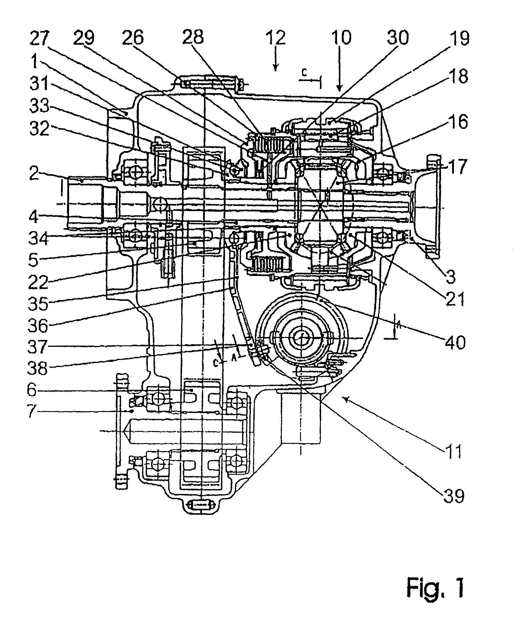
[0041]In FIG. 1, the housing of a transfer gear is referred to overall by 1, an input shaft coming from the drive unit (not illustrated) of the vehicle by 2, a first output shaft drive-connected to the rear axle by 3, and a second output shaft drive-connected to the front axle (likewise not illustrated) by 4. The second output shaft 4 uses a first toothed chain wheel 5 to drive a second toothed chain wheel 6 below the input shaft 2, said second toothed chain wheel sitting on a driven shaft 7 for the drive of the front axle.

[0042]To distribute the torque to the two output shafts 3, 4, a differential gear referred to summarily by 10 is provided. Furthermore, a control unit 11 below the differential gear 10 and a locking clutch 12 for locking the differential gear 10 are provided. In the exemplary embodiment shown, the locking clutch is structurally combined with the differential gear 10. However, it could also be separate, even arranged elsewhere in the transfer gear or in the drive t...


PUM


Abstract

A device for setting the torque transmitted by a friction clutch (12), having an actuator chain which comprises an electric motor (45), a step-down gear (42) and a mechanism for converting the rotational movement into a displacement of a pressure plate (29) of the clutch (12), so as to enable the torque which is transmitted to be set precisely and rapidly even given high friction. For this purpose, the electric motor (45) and / or step-down gear (42) is / are affected by friction, the conversion mechanism (31, 32, 35, 36, 40) and / or the friction clutch (12) itself is / are affected by elasticity, and, to set the torque (Md) of the friction clutch (12), a position regulator (47) which is operatively connected to the electric motor (45) and a sensor (46; 46′) which determines the position of one of the links of the actuator chain (45, 42, 41, 40, 36, 35, 32, 31, 29) are provided, the sensor being present at a location upstream of a substantial part of the elasticity in the force-flow direction. The corresponding control and calibrating method is also developed.

Description

BACKGROUND OF THE INVENTION[0001]The invention relates to a device for setting the torque transmitted by a friction clutch, having an actuator chain which comprises an electric motor, a step-down gear and a mechanism for converting the rotational movement into a displacement of a pressure plate of the clutch. Friction clutches having a torque which can be set and transmitted are used, for example, in drive trains of motor vehicles, in particular all-wheel drive motor vehicles, as a differential lock or for switching on an axle drive.[0002]This means not only controlled engagement of the friction clutch but also prolonged operation with the torque set precisely, in accordance with the torque which is to be transmitted. In this case, the torque which is transmitted can be varied continuously by means of a regulating or control device in accordance with dynamic driving requirements. High torques to be transmitted require considerable pressure forces and therefore actuating forces, incr...

Claims


Application Information

Patent Timeline
Patent Type & Authority Patents(United States)
IPC IPC(8): F16H1/00F16H1/14B60K17/35F16D27/00F16D27/115F16D28/00F16D48/06F16H1/16
CPCF16D48/064F16D28/00F16D27/115B60W2710/027F16D48/066F16D2500/1024F16D2500/3067F16D2500/30816F16D2500/30825F16D2500/70223F16D2500/70241F16D2500/70252F16D2500/70264F16D2500/7041F16D2500/7044F16D2500/70605
Inventor PARIGGER, MARTIN
Owner MAGNA STEYR POWERTRAIN
Why Eureka
Try Eureka