Electrical isolation connector subassembly for use in directional drilling

a technology of directional drilling and sub-assembly, which is applied in the direction of thermal insulation, flexible pipes, pipes, etc., can solve the problems of sub-assembly connectors, sub-assemblies are subjected to extreme torsional compression, bending, and failure of external devices, and achieves a smaller gap region, enhanced strength characteristics, and more robust design

Inactive Publication Date: 2006-04-25
RYAN ENERGY TECH
View PDF11 Cites 13 Cited by
  • Summary
  • Abstract
  • Description
  • Claims
  • Application Information

AI Technical Summary

Benefits of technology

[0007]In accordance with an aspect of this invention, provided is an electrical isolation connector subassembly for use in data telemetry in directional drilling applications. The electrical isolation connector subassembly of the current invention has enhanced strength characteristics due to a more robust design, and incorporates a considerably smaller gap region between the electrically isolated adjacent drill string components, thereby reducing the amount of wear to the insulative surfaces and eliminating the need for a protective wrapping.

Problems solved by technology

The problem with mounting communication devices and sensing devices on the exterior of the drill string is that particularly with directional drilling the exterior devices are damaged by striking the formations about the bore hole.
The various types of subassemblies provide for electrical isolation which are particularly useful in bore hole inspection, but may be subject to failure when used, for example, in directional drilling.
It has been found that the drill string, and in particular the subassembly connector, is subjected to extreme torsional compression, tension, and bending moments during directional drilling.
Such extreme forces can result in connector failure, usually at the weakest point in the subassembly.
The connectors of these patents and patent application may fail due to overstressing and possibly break up at their weakest point.
These large gaps require a protective wrapping, as the abrasive conditions during drilling can quickly damage the insulative materials used in these gaps.
However, the protective wrapping is also subject to extreme abrasive forces and are consequently prone to frequent failure, thus necessitating frequent replacement.

Method used


Image

  • Electrical isolation connector subassembly for use in directional drilling
  • Electrical isolation connector subassembly for use in directional drilling
  • Electrical isolation connector subassembly for use in directional drilling

Examples


Embodiment Construction

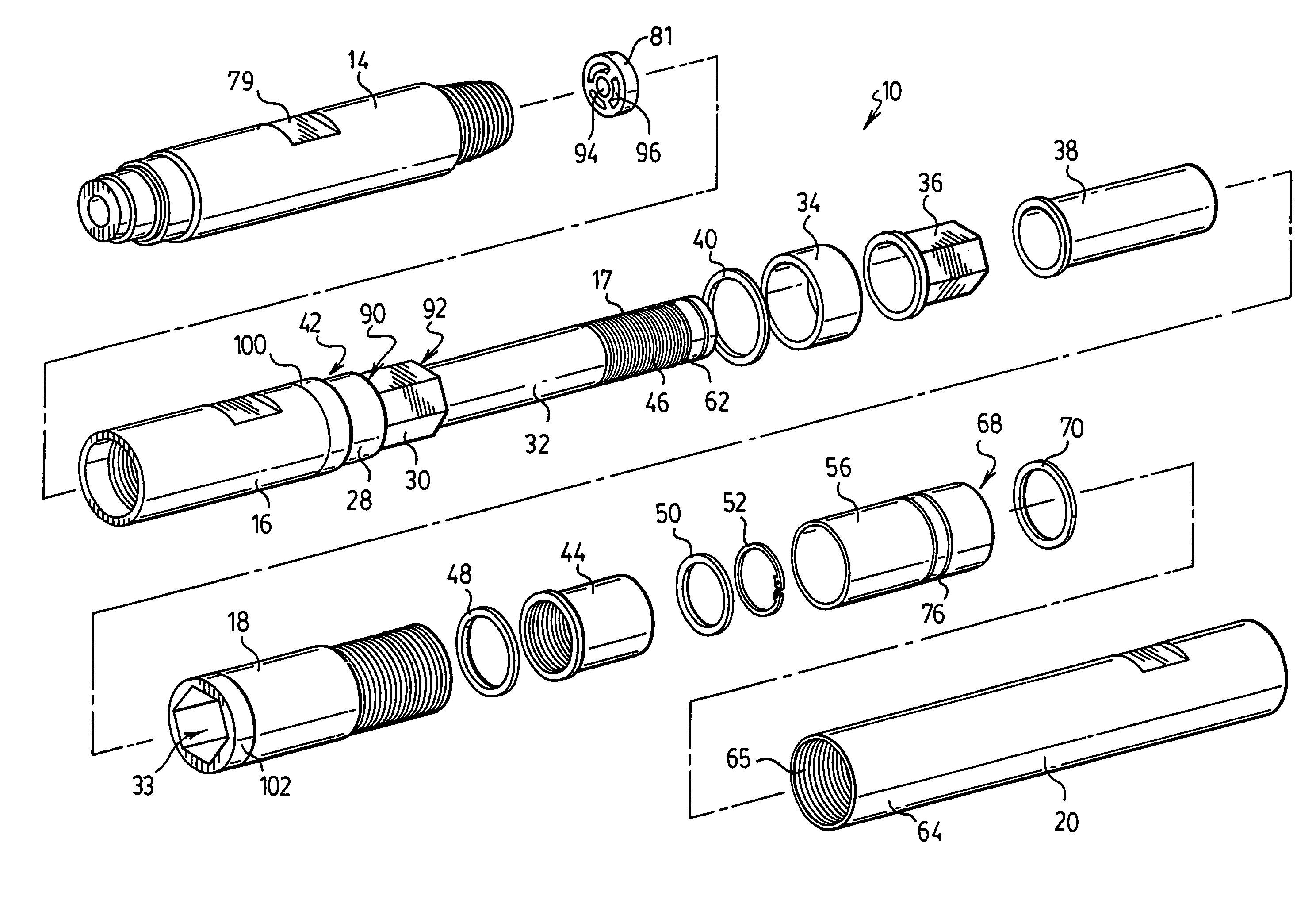
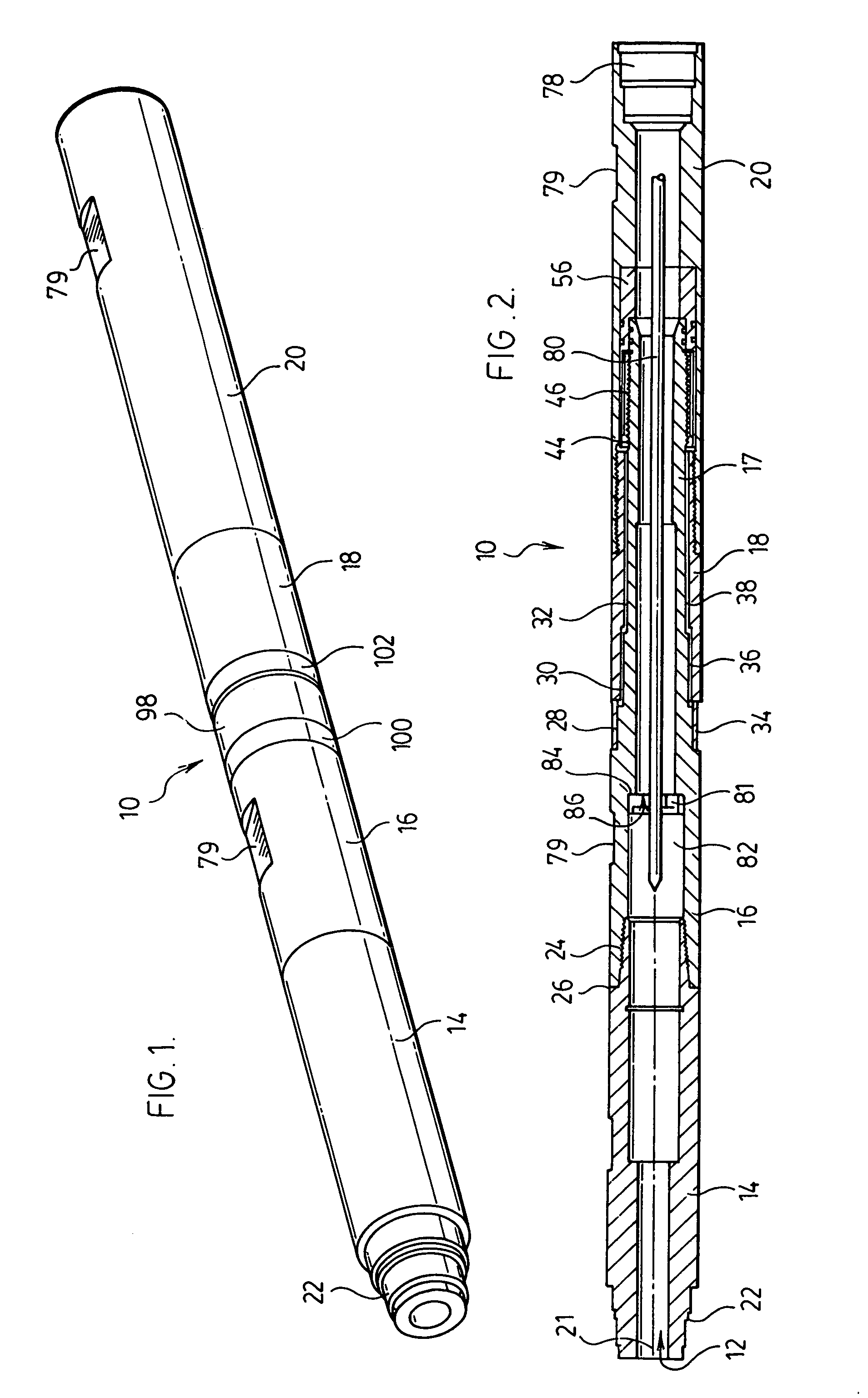
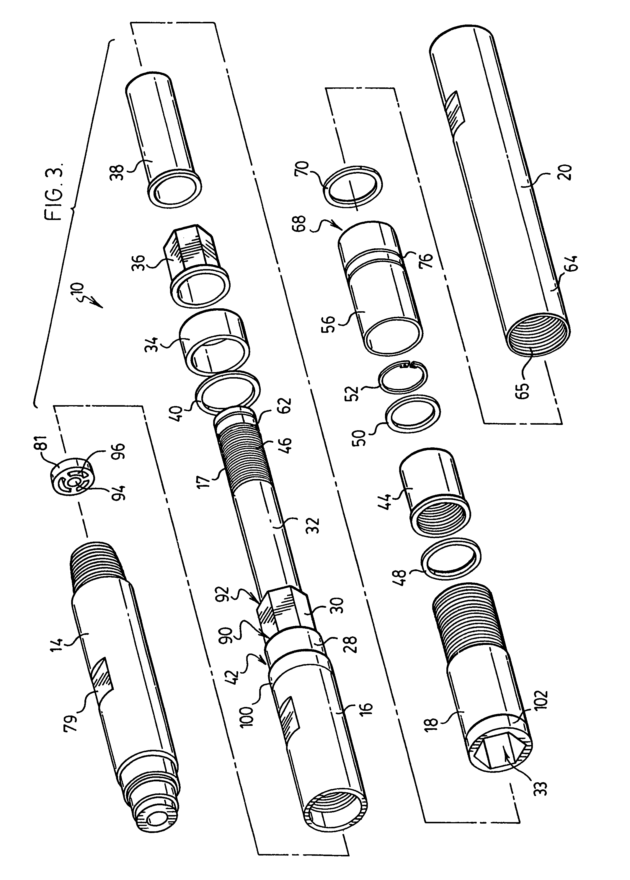
[0034]Various aspects of the invention are described in detail where it is appreciated that the principles of the invention, as established in the detailed description of the drawings, may find application for use in data telemetry during directional drilling operations. The purpose of the invention is to electrically isolate drill rod components so as to form an antenna, preferably adjacent the location of the drill bit. The antenna transmits electromagnetic data signals to the earth surface that are interpreted and used for various informational purposes, such as for the inspection and evaluation of bore holes. Quite surprisingly, applicant has found that the external gap between the electrically isolated components can actually be less than 50 cm. This was never thought possible as per the prior art. By virtue of this shortened external gap the invention can provide a robust drilling subassembly. This shortened external gap greatly facilitates manufacture and assembly of the suba...


PUM


Abstract

An electrical isolation connector subassembly for interconnecting adjacent tubular drill rods of a drilling system used in drilling bore holes in earth formations, the connector comprising an electrically insulative sleeve being sandwiched between two electrically isolated subassembly components, the sleeve providing an exterior gap between the edges of the spaced apart electrically isolated components, the exterior gap having a width of less than 50 cm.

Description

FIELD OF THE INVENTION[0001]This invention relates to an electrical isolation connector subassembly for use in data telemetry in directional drilling applications.BACKGROUND OF THE INVENTION[0002]The transmission of electromagnetic signals from a bore-hole to the earth surface is an effective method of communicating information during various types of drilling operations, such as measuring while drilling (MWD) and / or logging well drilling (LWD). The ability to communicate allows for the monitoring of drilling operations, as well as the inspection and evaluation of surrounding geology. During directional drilling operations, such as boring holes under river beds, subways, unusual earth formations and tapping oil reservoirs, it is particularly important at all times to know precisely the location of the drill bit. A significant effort has been made to develop electrical instruments which are capable of transmitting signals at the drill face or inspection face back to the earth's surfa...

Claims


Application Information

Patent Timeline
Patent Type & Authority Patents(United States)
IPC IPC(8): F16L11/12E21B17/00
CPCE21B17/003
Inventor SUTHERLAND, MICHAEL T.GURJAR, RISHI
Owner RYAN ENERGY TECH
Why Eureka
Try Eureka