Underwater pelletizer with positively controlled cutter HUB

Active Publication Date: 2006-04-25
GALA INDUSTRIES INC
View PDF28 Cites 122 Cited by
  • Summary
  • Abstract
  • Description
  • Claims
  • Application Information

AI Technical Summary

Benefits of technology

[0007]This invention provides a positive control of the positions of a

Problems solved by technology

This structure provides an axial force to move the cutter hub and blades toward the die plate but does not provide any force to move the cutter hub and blades axially away

Method used


Image

  • Underwater pelletizer with positively controlled cutter HUB
  • Underwater pelletizer with positively controlled cutter HUB
  • Underwater pelletizer with positively controlled cutter HUB

Examples


Example

[0024]Although only one preferred embodiment of the invention is explained in detail, it is to be understood that the embodiment is given by way of illustration only. It is not intended that the invention be limited in its scope to the details of constructions and arrangement of components set forth in the following description or illustrated in the drawings. Also, in describing the preferred embodiment, specific terminology will be resorted to for the sake of clarity. It is to be understood that each specific term includes all technical equivalents which operate in a similar manner to accomplish a similar purpose.

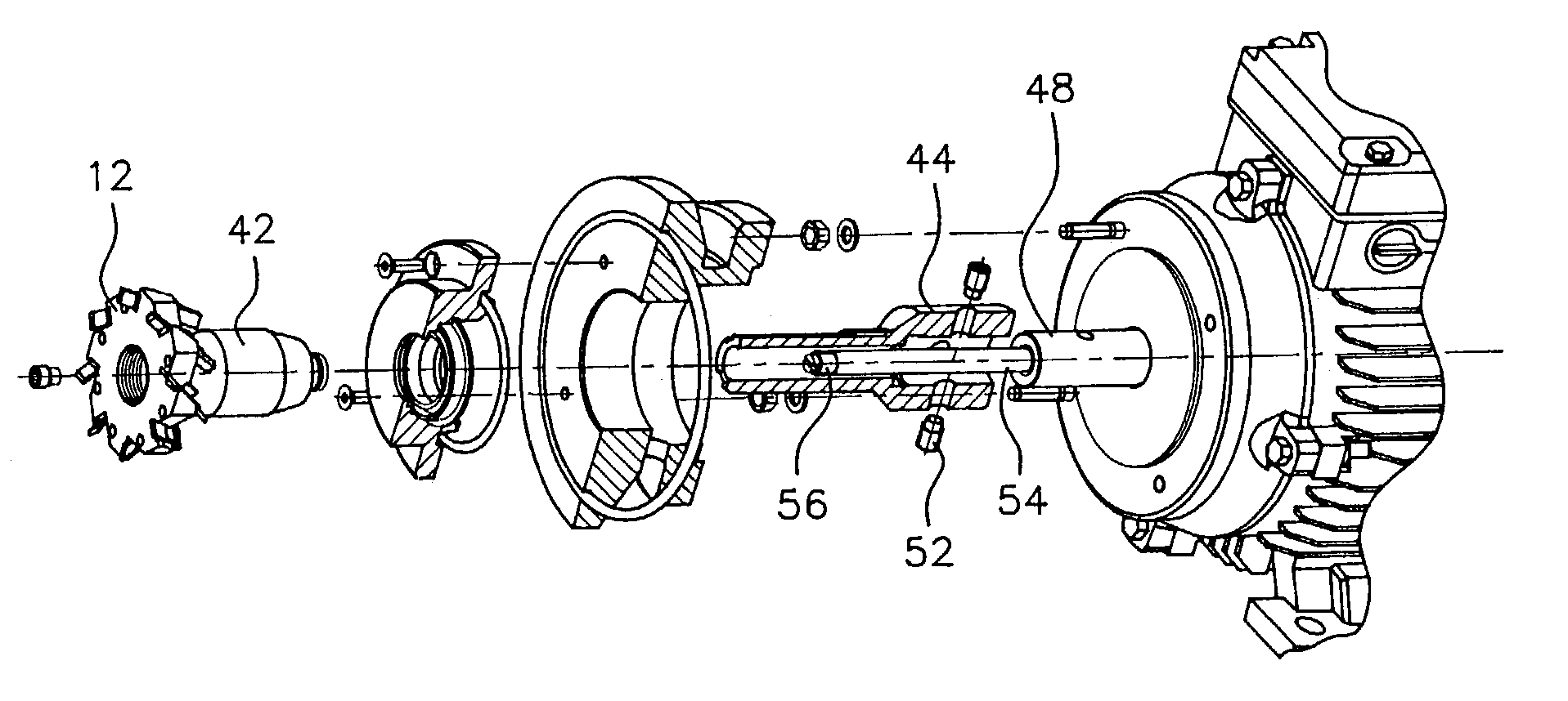
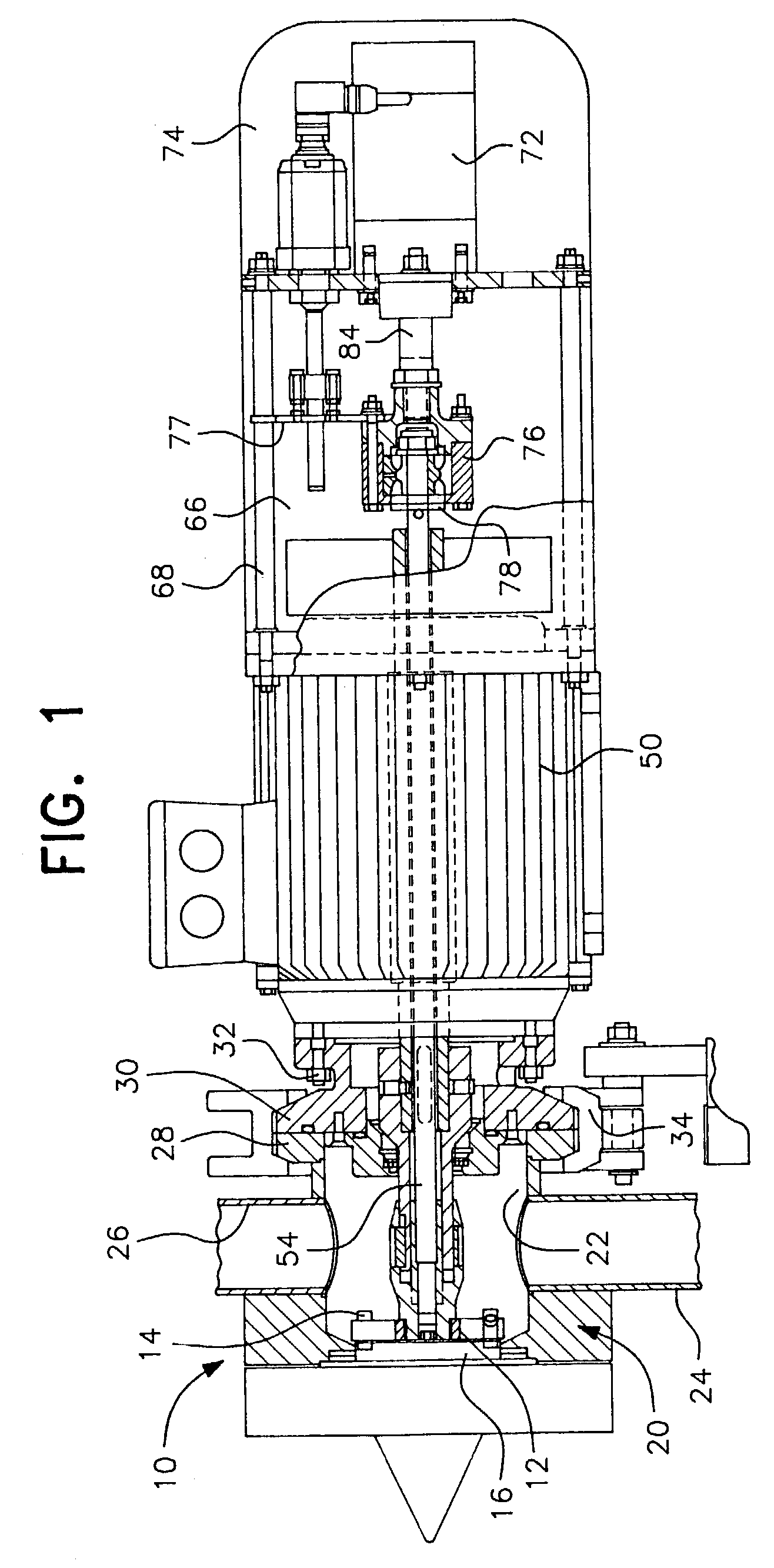
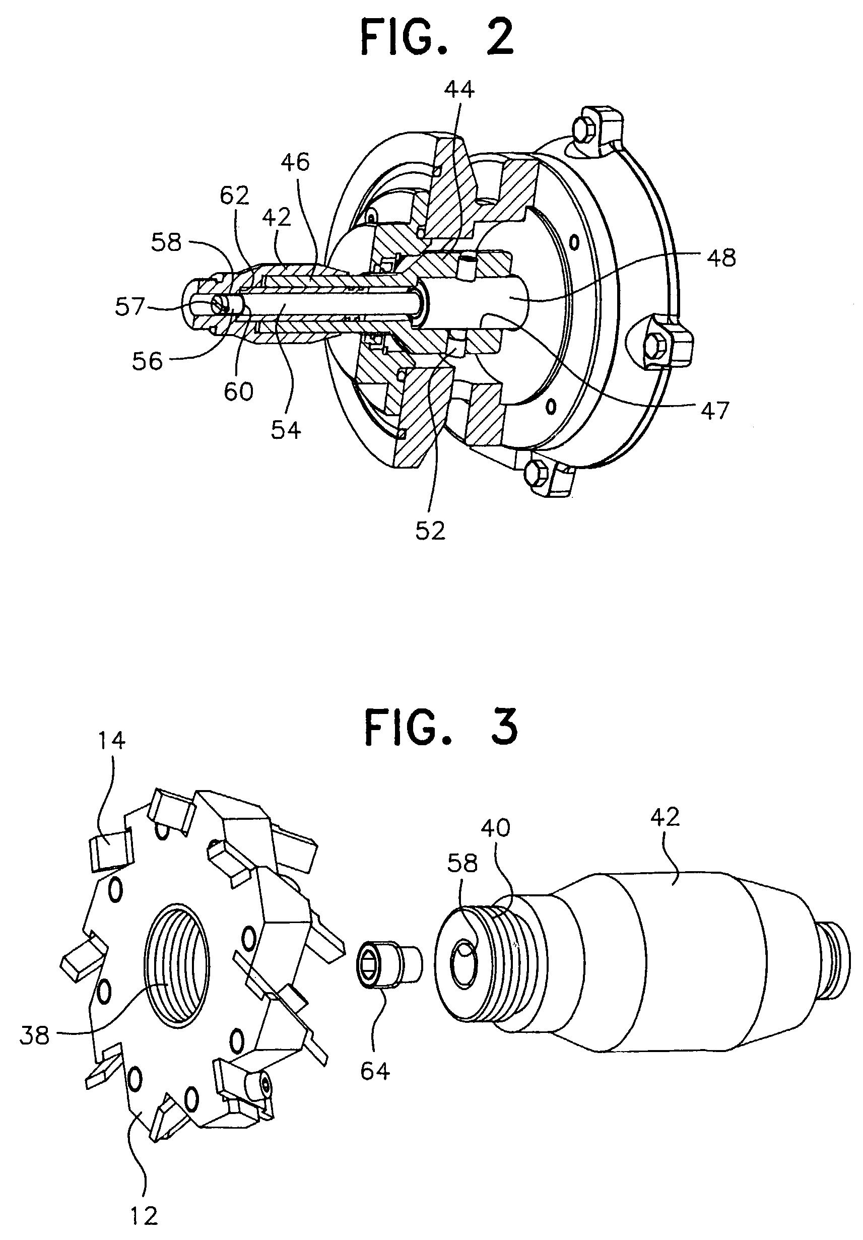
[0025]An underwater pelletizer constructed in accordance with the present invention is generally designated by reference numeral 10 in FIG. 1. The pelletizer 10 includes a rotatable cutter hub 12 supporting a plurality of cutter blades 14 associated with the die face of a die plate 16 through which molten polymer or other extrudable material is extruded through extrusion o...


PUM

PropertyMeasurementUnit
Pressureaaaaaaaaaa

Abstract

A cutter hub and blade assembly supported and driven for rotational and axial movement in relation to the die face of a die plate in an underwater pelletizer including a positive control of such axial movement to obtain and maintain optimal axial position of the cutter hub and blades during the pelletizing operation and to minimize wear of the mechanical components involved. Positive control of the axial movement of the cutter hub and blades is obtained by a hydraulic/pneumatic actuation system controlling an elongated motion rod that extends through a driven hollow motor shaft. One end of the motion rod is connected with a hydraulic/pneumatic control and the other end of the rod is connected to a cutter hub holder that supports the cutter hub and blades for axial movement toward or away from the die face.

Description

CROSS-REFERENCE TO RELATED APPLICATION[0001]This is a complete utility application entitled to the priority and claiming the benefit of U.S. provisional application Ser. No. 60 / 378,660, filed May 9, 2002.BACKGROUND OF THE INVENTION[0002]1. Field of the Invention[0003]The present invention relates to an underwater pelletizer and more specifically to a cutter hub and blade assembly supported and driven for rotational movement and axial movement in relation to the die face of a die plate in an underwater pelletizer. The supporting and driving arrangement for the cutter hub and blades includes a positive control of axial movement of the cutter hub and blades in relation to the die face as the cutter hub and blades are moved toward and away from the die face to obtain and maintain axial adjusted positions of the cutter hub and blades to minimize wear on the mechanical components involved. Positive control of the axial movement of the cutter hub and blades is obtained by a hydraulic / pneum...

Claims


Application Information

Patent Timeline
IPC IPC(8): B29B9/06
CPCB29B9/065
Inventor ELOO, MICHAELVELTEL, JURGEN
Owner GALA INDUSTRIES INC
Why Eureka
Try Eureka