Dry ice blasting cleaning apparatus

a cleaning apparatus and dry ice technology, applied in the direction of blast generating devices, cleaning processes and equipment, grinding machine components, etc., can solve the problems of affecting the cleaning effect of equipment, the bond between contaminants and the substrate surface of equipment to break, and the limited use of dry ice blasting cleaning devices

Inactive Publication Date: 2006-04-25
BRITISH COLUMBIA HYDRO & POWER AUTHORITY
View PDF14 Cites 83 Cited by
  • Summary
  • Abstract
  • Description
  • Claims
  • Application Information

AI Technical Summary

Benefits of technology

[0006]One general object of the invention is to provide an improved dry ice blasting cleaning apparatus. One particular objective is to provide a dry ice blasting cleaning apparatus that can operate for prolonged periods of time and without thawing periods. Another particular objective is to provide a dry ice blasting cleaning apparatus that is particularly suitable to clean energized electrical equipment such as EHV equipment.
[0007]According to one aspect of the invention, there is provided a dry ice blasting apparatus for cleaning electrical equipment, that comprises a cleaning wand and a heating mechanism for impeding the formation of condensation and / or frost on the outer surface of the wand, thereby enabling the wand to operate for prolonged periods of time. The cleaning wand comprises an elongated body having a handle portion at a proximal end of the body, a dry ice blasting stream passage extending at least partly through the length of the body and having an input end connectable to a dry ice blasting stream source and a discharge end at a distal end of the body, and a heating fluid cavity between the blasting stream passage and an outer surface of the body. The heating fluid cavity is configured to circulate a heating fluid therethrough. The heating mechanism comprises a fluid heater and pump fluidly coupled to the cavity and configured to heat and circulate a heating fluid through the cavity at a flow rate and temperature sufficient to impede condensation and frost from forming on the outer surface of the body when a dry ice blasting stream is flowing through the blasting stream passage. In particular, the heater and pump can be operated to circulate the heating fluid through the cavity at a flow rate and temperature sufficient to maintain the outer surface of the body above the ambient dew point.
[0010]The cavity can be annular and surround the dry ice blasting stream passage, thereby acting as a thermal insulator between the outer surface of the body and the passage. In particular, the annular cavity can be defined as the space between a pair of concentric, spaced tubes. The inside of the inner tube serves as the blasting stream passage, and the outside of the outer tube serves as the outer surface of the body. The outer surface of the body can have a smooth finish for encouraging water to bead on the surface.
[0011]The cleaning apparatus can further comprise an annular metallic corona ring coupled to the vicinity of the distal end of the body The corona ring has a sharp peripheral edge which generates negative corona, thereby preventing positive corona from contacting the outside surface of the outer tube and causing damage.

Problems solved by technology

The dry ice blasting stream instantly freezes contaminants on the equipment, causing the bond between the contaminants and the substrate surface of the equipment to break.
However, known dry ice blasting cleaning devices are limited to cleaning equipment energized at relatively low voltages of usually under about 50 kV, such as pad-mounted switchgear.
As such thaw periods add considerable delay to the cleaning process, operators can use multiple cleaning wands in staggered time intervals to minimize the delay.
While some low voltage electrical devices are relatively small and can be cleaned in under ten minutes, EHV electrical equipment energized to up to 500 kV are typically larger and thus take longer to clean.
Furthermore, energized EHV equipment produce much larger electric fields which require a farther safe operating distance than low voltage equipment.
Known dry ice blasting cleaning devices are not built with lengths or operating periods that are suitable to safely clean such energized EHV equipment.

Method used


Image

  • Dry ice blasting cleaning apparatus
  • Dry ice blasting cleaning apparatus
  • Dry ice blasting cleaning apparatus

Examples


Embodiment Construction

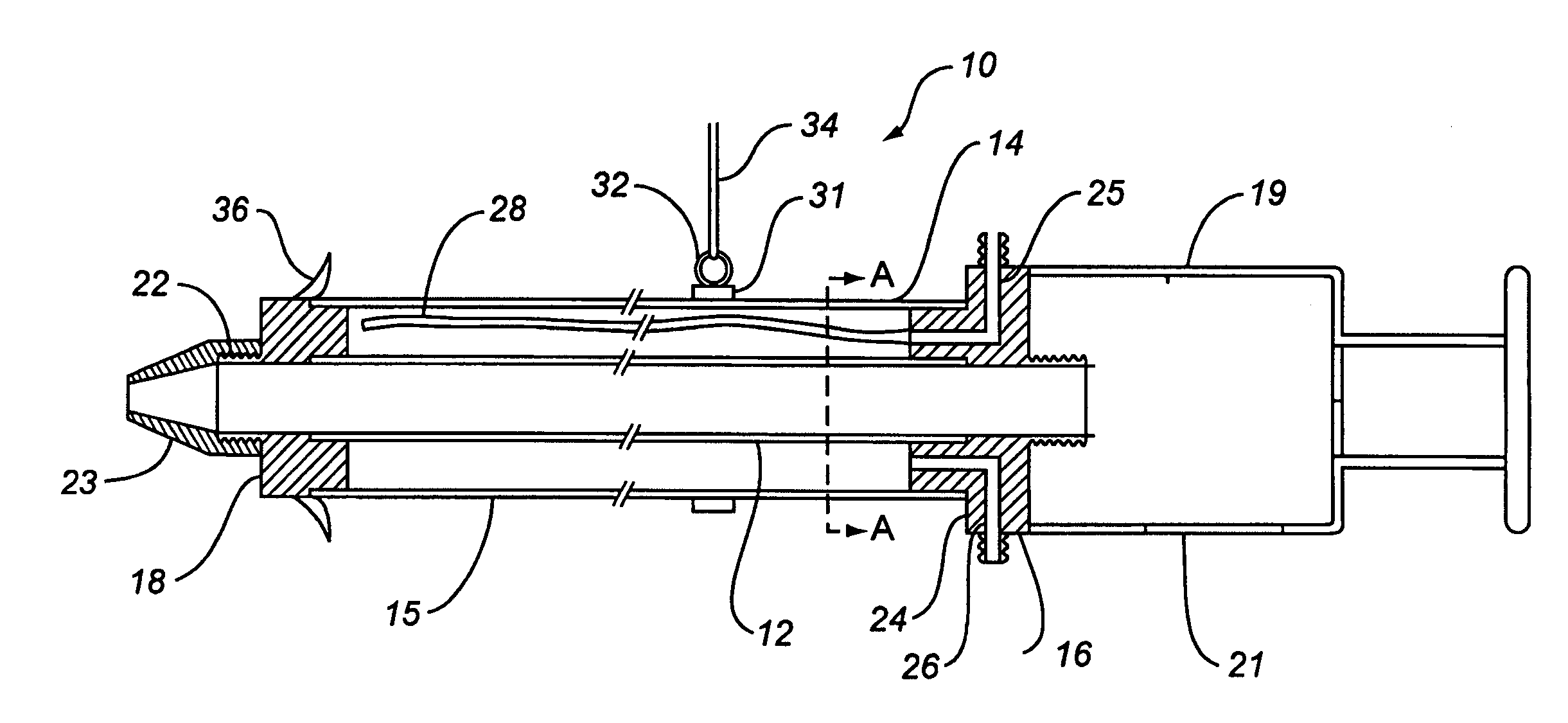
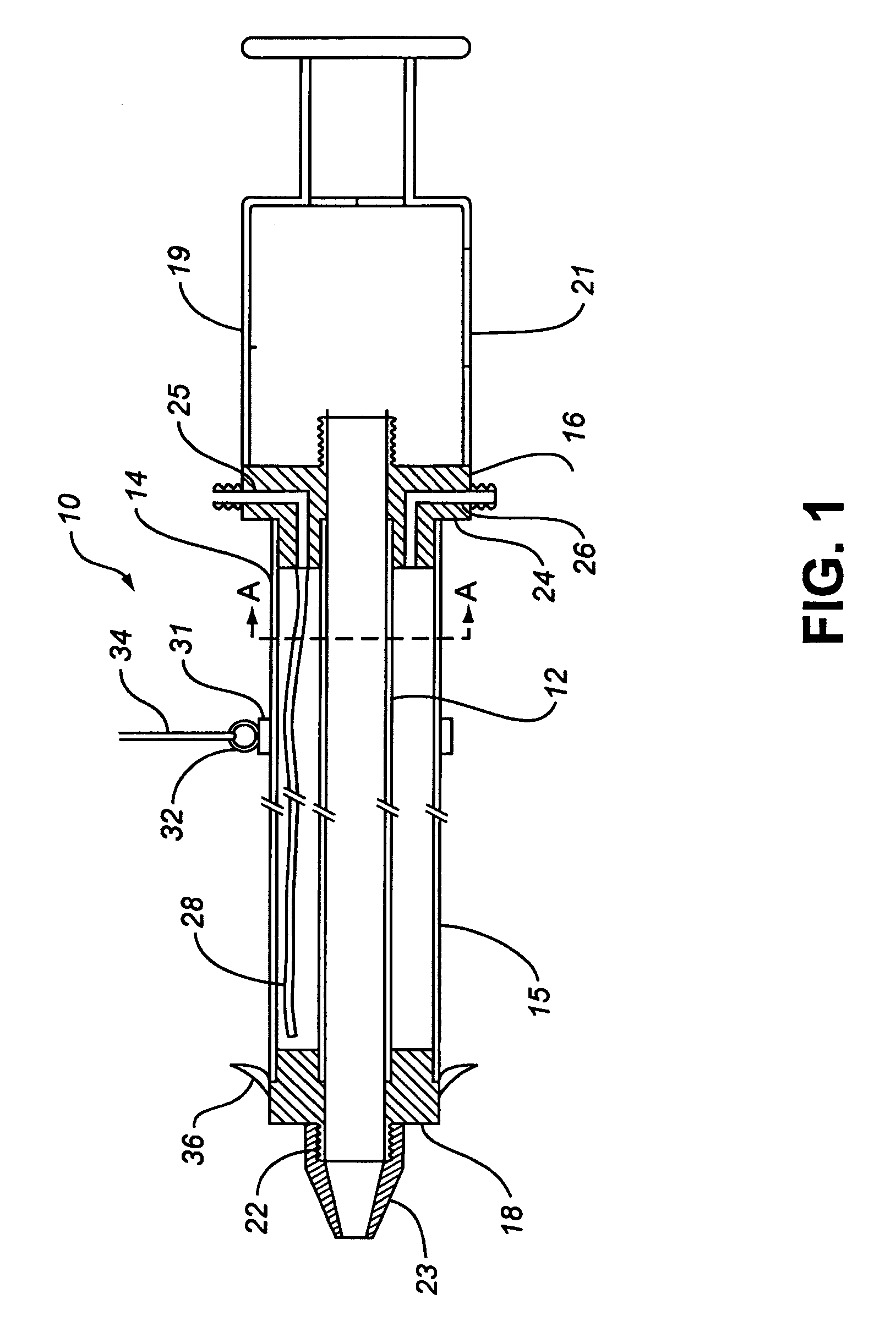
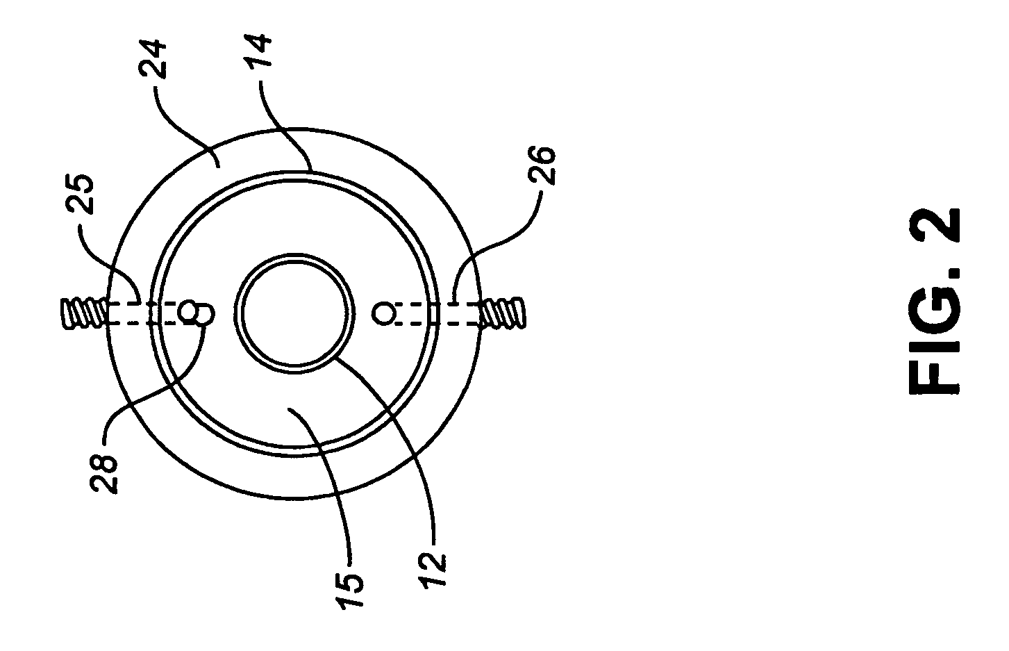
[0016]Referring to FIGS. 1 to 3 and according to one embodiment of the invention, there is provided a dry ice blasting cleaning apparatus 1 for cleaning energized electrical equipment up to 500 kV. The apparatus 1 comprises a cleaning wand 10 with a heating mechanism that resists condensation and frost build-up on the outside of the cleaning wand 10, and thus enables the cleaning wand 10 to safely operate for a prolonged period of time without a thaw-out period. In particular, the cleaning wand 10 comprises a cylindrical inner tube 12 and a cylindrical outer tube 14 arranged concentrically around and spaced from the inner tube 12 to define an annular heating cavity 15 for receiving a heatable dielectric fluid, such as Univis J13 hydraulic oil. The inner and outer tubes 12, 14 are comprised of suitably dielectric material sufficient to achieve the dielectric properties necessary for the cleaning wand 10 to operate in proximity to energized EHV equipment for the purpose of cleaning th...


PUM

PropertyMeasurementUnit
voltagesaaaaaaaaaa
voltageaaaaaaaaaa
lengthaaaaaaaaaa

Abstract

The invention is an apparatus used for cleaning equipment including extremely high voltage energized electrical equipment using a dry ice blasting stream as the cleaning agent. The apparatus comprises a cleaning wand and a heating mechanism for impeding the formation of condensation and / or frost on the outer surface of the wand, thereby enabling the wand to operate for prolonged periods of time.

Description

FIELD OF THE INVENTION[0001]This invention relates generally to a dry ice blasting apparatus for cleaning equipment and parts, such as energized high voltage (EHV) electrical equipment.BACKGROUND OF THE INVENTION[0002]Cleaning by dry ice blasting is a relatively new process that has quickly become a popular alternative to traditional cleaning methods such as steam cleaning, sandblasting, and cleaning with solvents. Dry ice blasting involves the discharge of a blasting stream substantially comprising dry ice (CO2) particles and a carrier stream of gas under pressure. The gas is usually air, although other gases such as nitrogen, carbon dioxide, or argon can also be used.[0003]Dry ice blasting can be used to clean equipment and parts in many different industries, such as automotive, aerospace, food processing, marine and electrical industries. Dry ice blasting is particularly desirable for cleaning electrical equipment in the utilities industry, as it can provide a moistureless blasti...

Claims


Application Information

Patent Timeline
Patent Type & Authority Patents(United States)
IPC IPC(8): B24B49/00B08B5/02B08B13/00B24C1/00B24C3/32B24C5/02
CPCB24C1/003B24C5/02B24C3/322
Inventor SPALTEHOLZ, BERNHARD ALEXANDERNIELSEN, GEOFFREY PAUL
Owner BRITISH COLUMBIA HYDRO & POWER AUTHORITY
Why Eureka
Try Eureka