Radio command device

a radio command and remote control technology, applied in the field of remote control of electric devices, can solve the problems of inability to test many products in the same location, difficulty in adjusting the product, and high equipment cost, and achieve the effects of limiting the personalization of products, avoiding interference during operation, and simple calibration of products

Inactive Publication Date: 2006-04-25
SOMFY SAS
View PDF16 Cites 28 Cited by
  • Summary
  • Abstract
  • Description
  • Claims
  • Application Information

AI Technical Summary

Benefits of technology

[0028]The invention applies equally to simple calibration of a product, for example, the end positions or intermediate positions along a race. The initial calibration or setup can also go to the overall program of the product. In effect, on the same generic base, many different products can differ by their management software. Due to the growth of memory capacity, some base products can contain many software applications. For reasons of standardization or programming, it can be advantageous to limit the personalization of products. The invention equally permits this type of product configuring at any stage of the cycle of production, stocking, or implementing, particularly those indicated above that have internal programs to be activated.
[0029]A second advantage is that it permits adjusting of these products and, more generally, the programs of products without communicating with the radio remote controls with which they are equipped.
[0030]Motorized products for different applications are similar products that have different behavior. Many products of different types with similar exteriors are processed alo

Problems solved by technology

On the other hand, it is problematic in the unitary testing of the apparatus or their presets in production.
It is not possible to test many products in the same location unless the testing is absolutely simultaneous such that the commands for one could b

Method used


Image

  • Radio command device
  • Radio command device
  • Radio command device

Examples


Embodiment Construction

[0061]In the embodiments which follow, various devices for implementing the present invention are described.

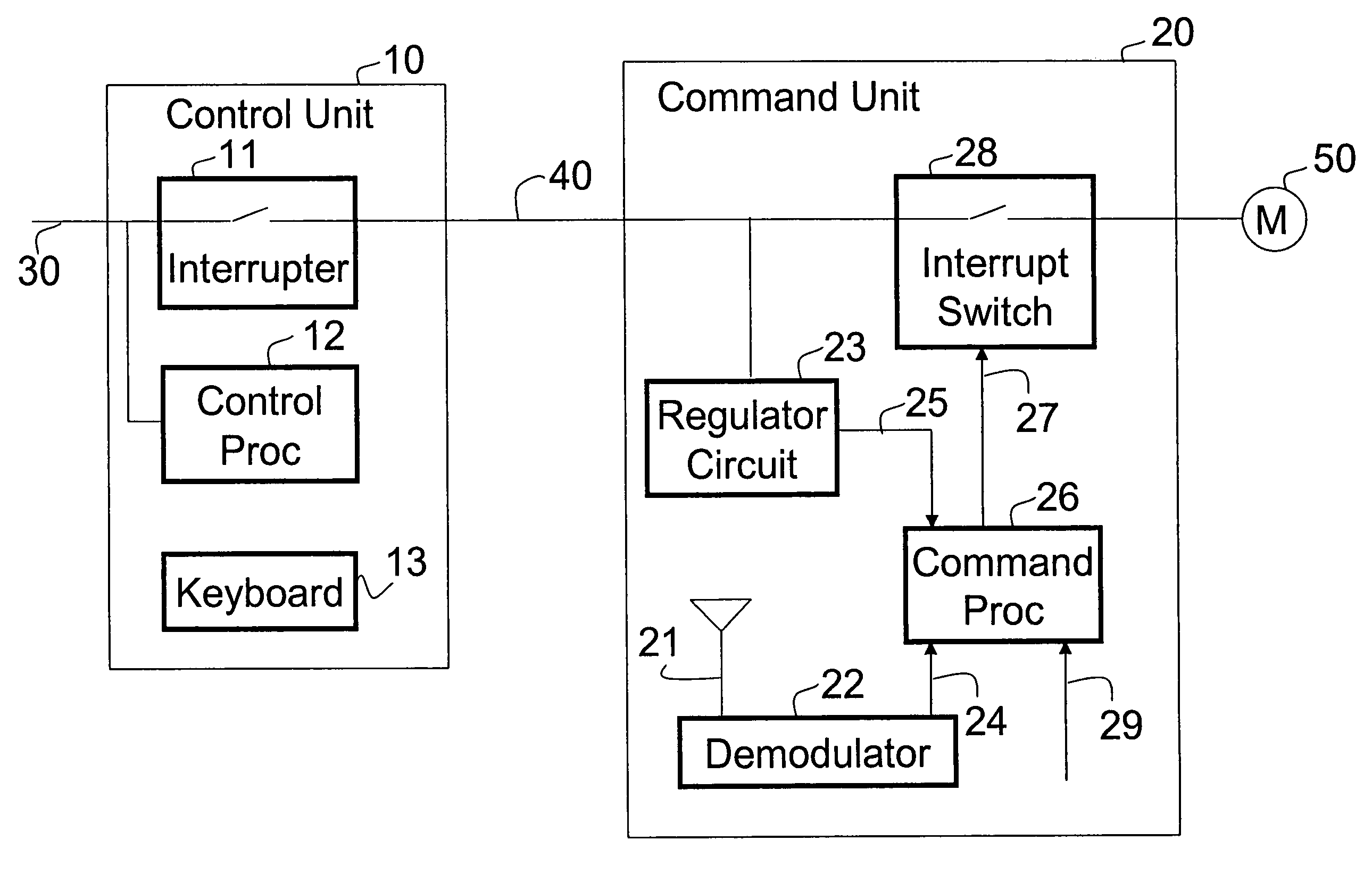
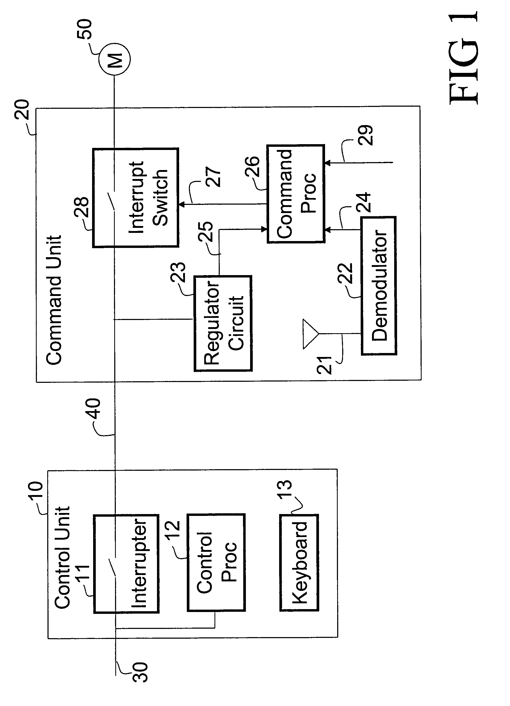
[0062]The schematic shown in FIG. 1 includes a control unit or console 10 which relies on an electrical interconnection 40 to a command unit 20 which controls an electric load 50 such as a motor M.

[0063]The control unit 10 is connected to an AC or alternate current supply 30 in such a manner that it causes interruptions in the current supplied to the command unit 20.

[0064]The control unit 10 includes a uni-directional or bi-directional controlled interrupter 11 whose opening is synchronized to the supplied AC current frequency and is controlled in accordance with a control sequence by a control processor 12. The control processor 12 is controlled by either a keyboard or an automatic programming unit 13. Under the control of the automatic programming or keyboard unit 13, a succession of breaks or gaps are caused in the AC line current which define elementary command signals or ...


PUM


Abstract

A control unit (10) superimposes command signals on AC power passing on a power line or network (40). A command unit (20) controls and powers an electrical load (50) such as a motor M. A command processor (26) receives radio frequency control signals at a first input (24) from an antenna (12) and a receiver/demodulator (22) and receives command signals from the power line at a second input (25) connected with a pulse shaping circuit (23). In a first, normal operating mode, the command processor controls the electrical load in accordance with signals received at the radio frequency input. In a second, special mode initiated power line command signals, the command processor at least temporarily blocks the execution of commands received at the radio frequency input.

Description

BACKGROUND OF THE INVENTION[0001]The present invention relates to the art of remote control of electric devices that are powered by electric current. It finds particular application in a process which permits an irregular remote command over electric supply lines that power the electrical device but which is normally controlled by radio. It also finds particular application in an apparatus for implementing this process.[0002]Similar electric devices are, for example, electric actuators for controlling solar shutters or other protection devices. The normal command is transmitted from a portable transmitter, a fixed transmitter, or a convenient meteorological sensor. In a normal radio command, it is also possible to initiate setup or adjustment modes which allow the installer or user to adjust the end position of a controlled operation, or to communicate the settings to new transmitters.[0003]Using radio transmissions for this type of application presents a number of advantages. On th...

Claims


Application Information

Patent Timeline
IPC IPC(8): H04N5/44G08C19/00G09G5/00H03J1/00H04B1/18H04Q9/00G08C17/02H04B1/00H04B3/54H04N5/00H04Q9/08
CPCG08C17/02H04B3/54H04Q9/08H04B2203/5458H04B2203/5441
Inventor SYMOEN, LIONELGAUTHIER, LAURENT
Owner SOMFY SAS
Why Eureka
Try Eureka