Drill pipe spinner device

a spinner device and drill pipe technology, applied in the direction of drilling pipes, wrenches, manufacturing tools, etc., can solve the problem of not being formed to allow centering, and achieve the effect of reducing the damage of threaded connections, increasing the risk of drill string breakdown, and great economic consequences

Inactive Publication Date: 2006-05-02
NAT OILWELL VARCO NORMAY AS
View PDF19 Cites 36 Cited by
  • Summary
  • Abstract
  • Description
  • Claims
  • Application Information

AI Technical Summary

Benefits of technology

[0015]A spinner of this kind comprises a frame part / structure with steering / guide rollers mounted on two vertical guides and comprising preferably four driven rotary rollers for the rotation of a drill pipe, said rotary rollers being manufactured from steel or a similar hard metal or metal alloy, and being driven by means of preferably hydraulic motors. According to the invention the driven rotary rollers are supported on bogies mounted on clamping arms, which are maneuvered by means of a maneuvered device in the form of a transverse hydraulic piston and cylinder or other actuator, parallel displacement stays and centering stays being arranged for said clamping arms.
[0016]For the spinner tongs a further piston and cylinder may be arranged, which exhibits sufficient lifting power to raise the spinner and drill pipe. Thereby the spinner and pipe section can be lifted free of the threaded potion when the pipes are being unscrewed from one another.
[0017]Said parallel displacement stays and centring stays may be provided with a spring-based centring unit, for example comprising two individual springs.
[0018]The device according to the invention is also formed with a view to reducing damage on the threaded connections as drill pipe sections are being screwed and unscrewed. Damage of the kind reduced or even eliminated through the present invention, has at all times represented an increased risk of drill string breakdown, with great economic consequences.

Problems solved by technology

An unfavorable common feature of known embodiments is, however, that they are not formed to allow centering of the drill pipe, which is to be lowered into the opposite box as two drill pipes are being screwed together.

Method used


Image

  • Drill pipe spinner device
  • Drill pipe spinner device
  • Drill pipe spinner device

Examples


Embodiment Construction

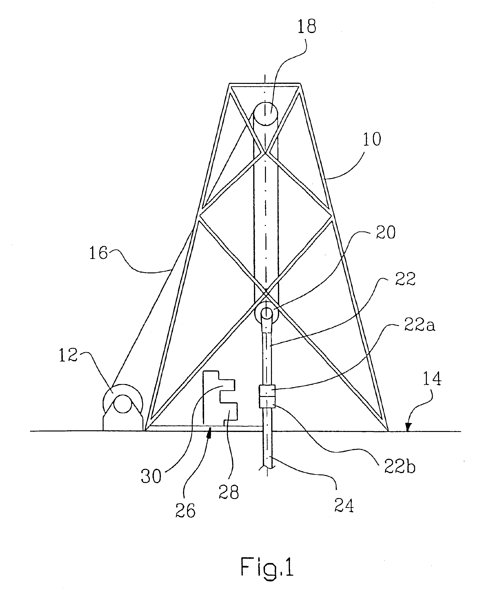
[0030]Reference is made to FIG. 1, in which the reference numeral 10 identifies a derrick with draw works 12 arranged thereto on the drill floor 14 of a platform, not shown in further detail, a wire line 16 leading from the draw works 12 up to a tackle 18 suspended from the derrick 10, and carrying through the wire line 16 an underlying tackle 20, from which the drill pipe length / section 22 is suspended.

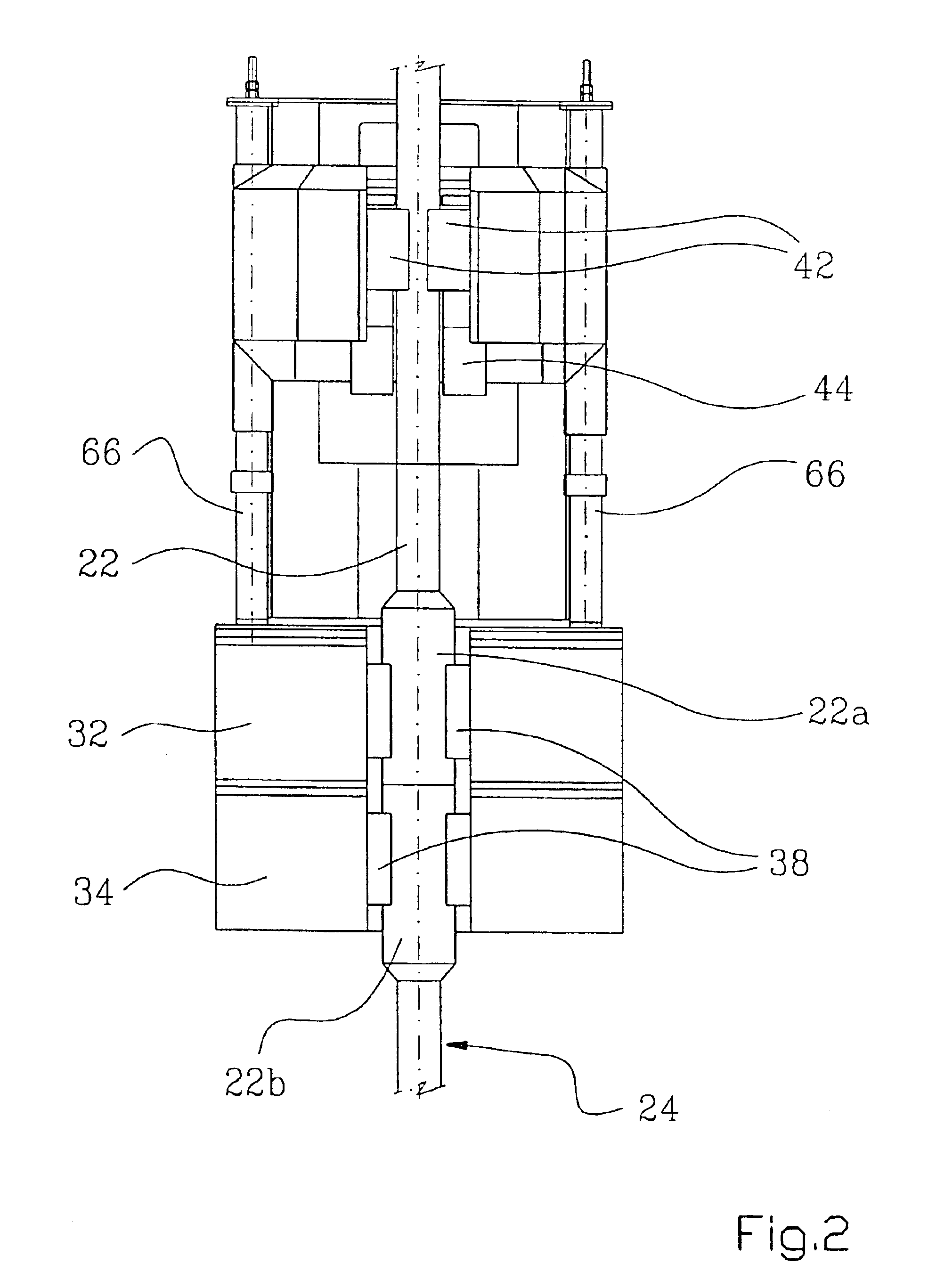
[0031]A number of such lengths / sections 22 of drill pipe are to be joined together through pin-and-box connections consisting of an upper part 22a and a lower part 22b in the form of a threaded male part, “a pin”, and a threaded female part, “a box”, for the formation of a continuous drill string 24.

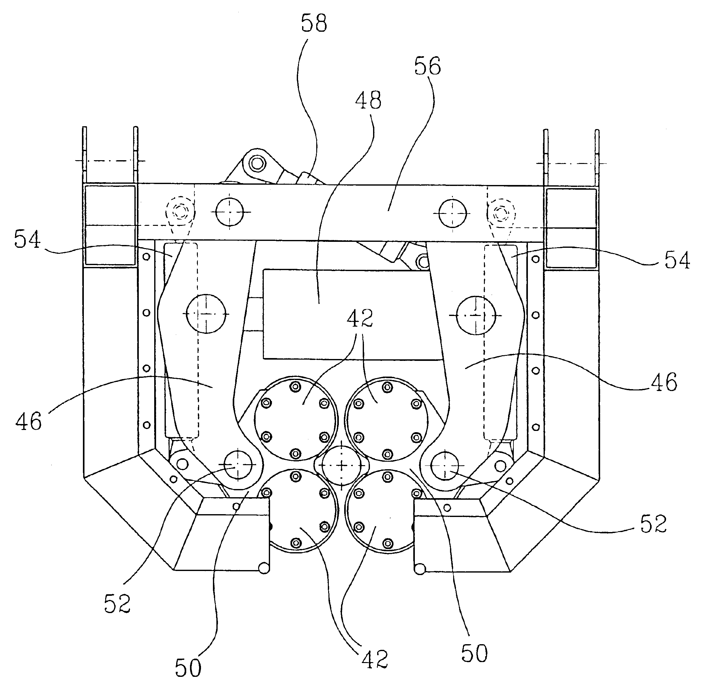
[0032]For screwing together the drill pipe lengths / sections 22 and tightening the threaded connections at the ends thereof, an iron roughneck is used, generally identified by the reference numeral 26, in principle comprising two main components, a lower component in the form of a torque w...


PUM


Abstract

In spinner tongs, a so-called spinner (30), incorporated in an iron roughneck and thus serving to rotate a drill pipe during connection thereof to a drill string or during division of the drill string into individual pipes, the aim has been to reduce damage on the threaded connections (the pin-and-box joints) in the screwing/unscrewing operations. This is realised in an operation for the simultaneous centering and rotating of the drill pipe. Four spinner rollers (42) known in themselves, which are brought to bear on the drill pipe when surrounding it, are mounted according to the invention, preferably in pairs, at the outer ends of driven clamping arms (46), by bogies (50). At their opposite outer ends the clamping arms (46) are pivotally supported on a fixed frame part/structure (56) and are jointed to each other by means of a piston and cylinder (48) driven by pressure fluid and arranged to carry the clamping arms (46) towards and away from each other. For their forced centering the clamping arms (46) have a centering stay (58) arranged thereto, which is connected by its outer end to one clamping arm (46), and is connected by its other outer end to the other clamping arm (46). For the parallel displacement of the rollers (42), each bogie (50) has a parallel stay (54) arranged thereto, whose other end is supported on a fixed frame part/structure (56).

Description

CROSS REFERENCE TO RELATED APPLICATION[0001]The present application is the U.S. national stage application of International Application PCT / NO01 / 00171, filed Apr. 25, 2001, which international application was published on Nov. 8, 2001 as International Publication WO 01 / 83935. The International Application claims priority of Norwegian Patent Application 20002258, filed Apr. 28, 2000.SUMMARY OF THE INVENTION[0002]This invention relates to a spinner / spinner tong device for use in the screwing or unscrewing of threaded connections in the form of internally threaded box ends, each to be brought into engagement with / disengaged from an externally threaded pin end of an adjacent pipe length or pipe section, especially lengths of drill pipe of the kind being screwed together for the formation of a continuous drill string for use in connection with the drilling for oil and gas deposits.[0003]In the following a spinner indicates a spinner or spinner tongs, unless otherwise explicitly specified...

Claims


Application Information

Patent Timeline
Patent Type & Authority Patents(United States)
IPC IPC(8): B25B17/00E21B19/16
CPCE21B19/168
Inventor MOE, MAGNEHAUGHOM, PER OLAVPOLLESTAD, JORN
Owner NAT OILWELL VARCO NORMAY AS
Why Eureka
Try Eureka