Arrangement for mixing a first and a second gas flow

a gas flow and arrangement technology, applied in the direction of mixers, non-fuel substance addition to fuel, combustion process, etc., can solve the problems of complex situation with respect to exhaust gas cleaning technology, different operating cycle with higher load, and disadvantages in the form of complex and space-demanding components, etc., to achieve good regulation

Inactive Publication Date: 2006-05-02
VARIVENT INNOVATIONS
View PDF10 Cites 34 Cited by
  • Summary
  • Abstract
  • Description
  • Claims
  • Application Information

AI Technical Summary

Benefits of technology

[0009]One object of the present invention is to provide an arrangement of the type specified in the introduction that minimises pressure losses when mixing the two gases.
[0011]According to one aspect of the invention, the streamlined body and the supply part are designed to achieve maximal throttling in the line close to the inlet, independently of the position of the body. In other words, the momentary throttle effect of the first flow will then always be greatest in close proximity to the inlet independently of the displacement / location of the body in the direction of flow. The requirement for throttling, and thus the associated pressure losses, are in this way minimised.
[0012]A flow regulator for EGR systems in the form of a variable venturi has been developed on the basis of the present invention, intended for mounting in the inlet part of turbocharged diesel engines. The flow regulator comprises a pipe section with a radial EGR supply flow and an essentially freely suspended body in it. The body can be displaced in the direction of the flow and is preferably designed such that the instantaneous throttling of fresh air is always greatest in the immediate vicinity of the inlet for supply of exhaust gases, independently of the position of the body. Thus, it is included that the throttling varies optimally during the regulation as a consequence of the variation with respect to the flow area of fresh air between the body and the wall of the pipe during supply of exhaust gases. In this way, the varying requirement for pumping is satisfied, with a minimum of pressure losses.
[0014]The venturi effect is principally achieved through the design of the streamlined body, and can in particular cases be supplemented with a fixed venturi part, the diameter of which is either greater than or less than the greatest diameter of the drop section. An outlet cone (diffuser) can be incorporated with the rear part of the pipe section, as necessary, which makes its mounting possible in inlet channels with varying dimensions.
[0017]The properties of the body, its location in the inlet channel and the actuating means allow a minimal disturbance of the supply of air to be achieved, and very good regulation is achieved with thorough mixing of the air supply for varying loads on the engine.

Problems solved by technology

The situation with respect to exhaust gas cleaning technology is much more complex where turbocharged diesel engines with heavy operating conditions are concerned.
Furthermore, these engines have a different operating cycle with higher loads during certification.
Several solutions have been suggested, including expensive catalysis processes including several subprocesses (for example, injection of water, addition of urea) that in addition involve disadvantages in the form of complex and space-demanding components.
However, these solutions have up until now been associated with disadvantages in the form of, for example, a reduced engine power through high pressure losses, together with increased fuel consumption and smoke development.
This control valve cannot be used in the inlet channels of turbocharged engines, not least as a result of its design.
The opening for supply of exhaust gases is not located where the throttling of fresh air is greatest, which would involve a more severe throttling than necessary, while the total pressure losses, which arise from, for example, the neighbouring actuating means, become significant.
The design does not display a proper venturi shape since the fresh air is exposed to a momentary increase in area at the end of the injector pipe, and the pressure losses that follow from this.
The component must be equipped with an elbow, with its associated pressure losses, as a result of the axial supply, and furthermore, the fact that the dimensions of the component are unnecessarily bulky must also be considered.

Method used


Image

  • Arrangement for mixing a first and a second gas flow
  • Arrangement for mixing a first and a second gas flow
  • Arrangement for mixing a first and a second gas flow

Examples


Embodiment Construction

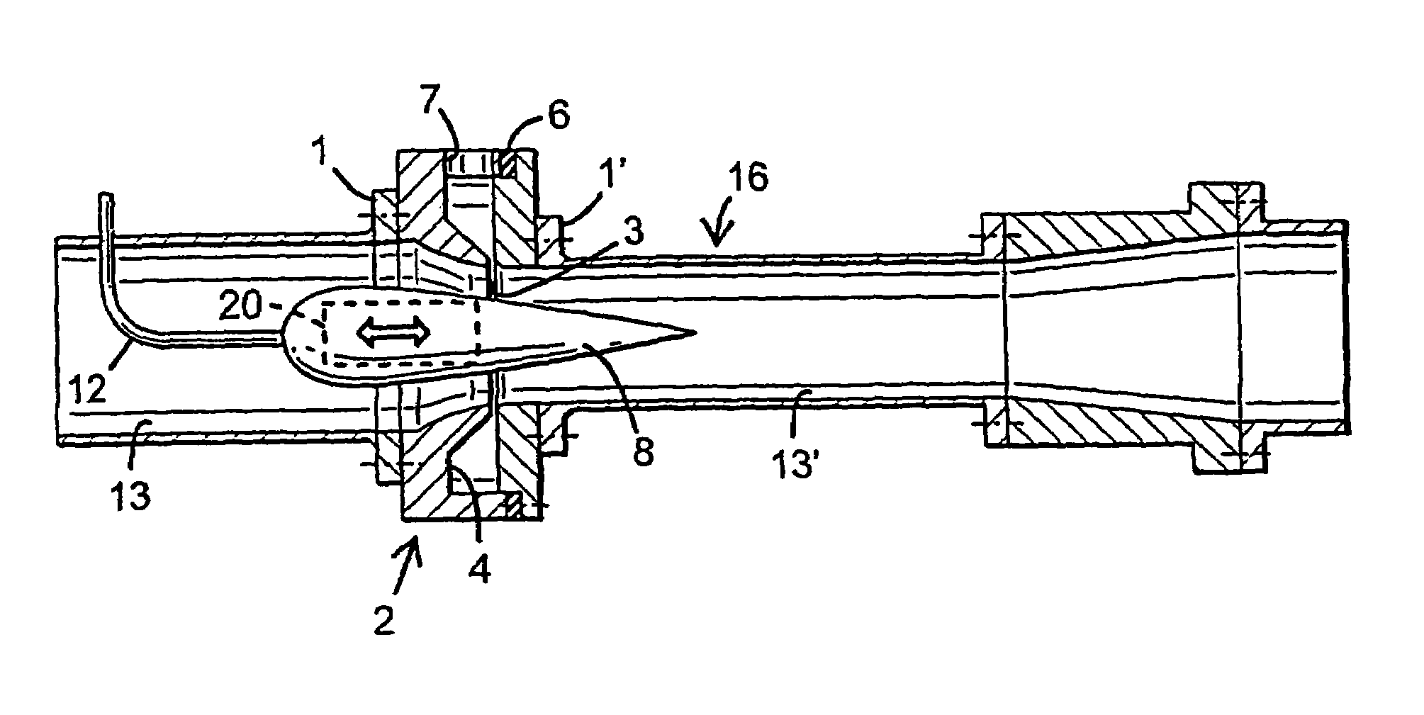
[0025]Embodiments of the invention will be described in the following text as preferred embodiments in association with exhaust gas recirculation of a turbocharged diesel engine. The invention, however, is not limited to this, but can be used in many different applications where two gas flows are to be mixed. One example is oxygen-enrichment, that is, supply of oxygen to another gas. The area of application can in this case be, for example, refuse combustion plants.

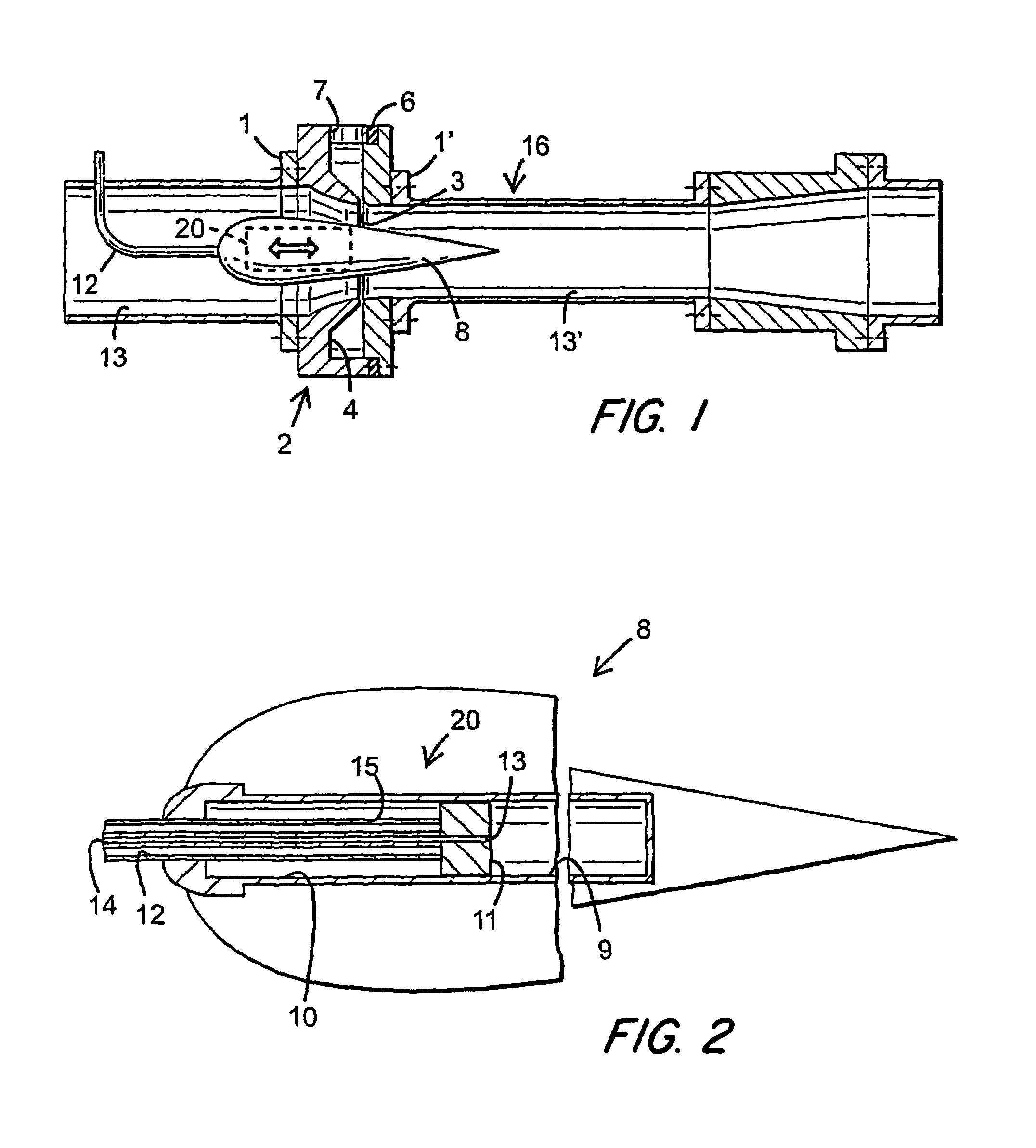
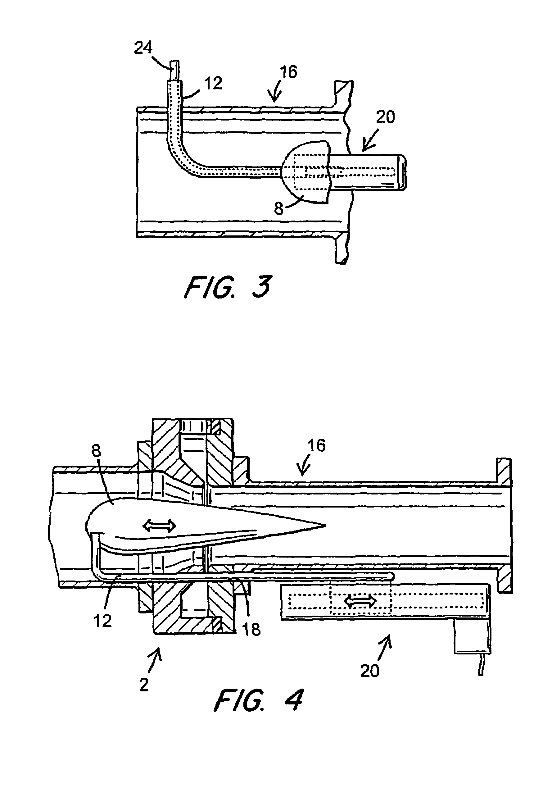
[0026]In the preferred application, an EGR supply flow is introduced radially via a supply part 2 in an inlet channel or pipeline generally denoted by 16 from a turbocharger that is not shown. The supply part 2 is inserted between flanges 1, 1′ of a pair of pipe sections 13 and 13′ in the line 16. The supply part 2 forms a flow regulator together with the streamlined body 8 described below. On the basis of the designs of the streamlined body 8 and the supply part 2, the greatest throttling of fresh air is always achieved ...


PUM

PropertyMeasurementUnit
areaaaaaaaaaaa
pressureaaaaaaaaaa
gap widthaaaaaaaaaa

Abstract

An arrangement for mixing a first and a second gas flow, for example, an inlet flow with a exhaust gas return flow in a diesel engine, comprising a line (16) for the first flow, an inlet (7) for the second flow in the line (16), in order to achieve the mixing; a streamlined body (8) arranged to be displaced in the longitudinal direction of the line (16) at the inlet (7) in order to achieve a variable venturi effect and in this way a variable suction effect and mixture of the mixed flow; and actuating means for displacing the body forwards and backwards in the line. In order to minimise the need for throttling and the accompanying pressure losses, the streamlined body (8) and the supply part (2) are designed to achieve maximal throttling in the line (16) close to the inlet (7), independently of the position of the body.

Description

TECHNICAL FIELD[0001]The present invention concerns an arrangement for mixing a first and a second gas flow, for example, an input flow and a exhaust gas return flow in a diesel engine, comprising a line for the first gas flow, an inlet in the line for the second gas flow in order to achieve mixing, a streamlined body that can be displaced in the longitudinal direction of the line at the inlet in order to achieve a variable venturi effect and in this way a variable suction effect and mixing of the mixed flow, and actuating means for displacing the body forwards and backwards in the line.PRIOR ART[0002]As a result of expected stricter legislation concerning the levels of nitrogen oxides (NOx) in exhaust gases from diesel engines, extensive development is currently being carried out at many locations to produce a system for the cleaning of exhaust gases and reduction of the NOx levels. Solutions that function well with respect to petrol engines and lighter diesel engines are available...

Claims


Application Information

Patent Timeline
Patent Type & Authority Patents(United States)
IPC IPC(8): G05D11/02F02M25/07B01F23/10F02D9/12
CPCF02D9/12F02M25/0722Y02T10/121F02M26/19Y10T137/3367Y10T137/87619F23D2203/007F23R3/286
Inventor BERGGREN, GUSTAVJANSSON, FREDRIKWESTIN, FREDRIKANG.NGSTROM, HANS-ERIK
Owner VARIVENT INNOVATIONS
Why Eureka
Try Eureka