Apparatus for producing self-exciting hammer action, and rotary power tool incorporating such apparatus

Inactive Publication Date: 2006-05-02
BLACK & DECKER INC
View PDF20 Cites 14 Cited by
  • Summary
  • Abstract
  • Description
  • Claims
  • Application Information

AI Technical Summary

Benefits of technology

[0012]The second clutch member may include a substantially frustoconical outer surface adapted to frictionally engage a corresponding surface of said first clutch member. The cone angle of said substantially frustoconical outer surface is preferably not less than the friction angle between said substantially frustoconical surface and the corresponding surface of said first clutch member. This provides the advantage of minimising the risk of the second clutch member becoming

Problems solved by technology

As the rotational frequency of the drill changes, it is difficult to maintain the percussion action within its op

Method used


Image

  • Apparatus for producing self-exciting hammer action, and rotary power tool incorporating such apparatus
  • Apparatus for producing self-exciting hammer action, and rotary power tool incorporating such apparatus
  • Apparatus for producing self-exciting hammer action, and rotary power tool incorporating such apparatus

Examples


second embodiment

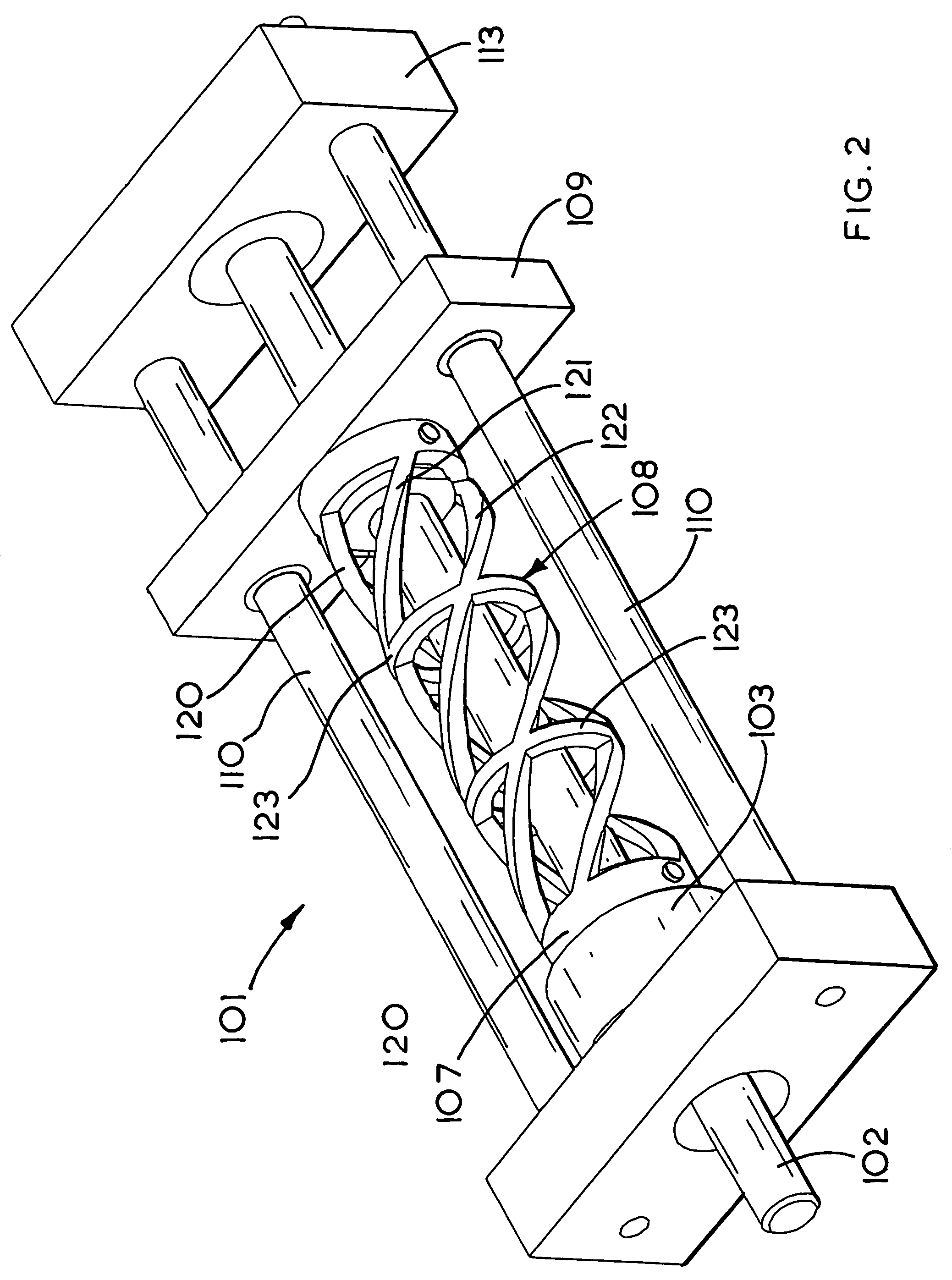
[0042]Referring now to FIGS. 2 to 4, in which parts common to the embodiment of FIG. 1 are denoted by like reference numerals but increased by 100, a hammer drill 101 of the invention has a first mass 107 connected to a second mass 109 by means of a helical spring 108 including three individual helices 120, 121, 122 which are connected together by means of a series of rings 123. The spring 108 of the embodiment of FIGS. 2 to 4 has the advantage of minimising radial expansion of the spring 108 as it acquires twist, which may otherwise reduce the extent to which the spring 108 converts rotary movement of first mass 107 into axial movement of second mass 109.

third embodiment

[0043]Referring to FIGS. 5 and 6, in which parts common to the embodiment of FIG. 1 are denoted by like reference numerals but increased by 200, a hammer drill 201 of the invention has a working shaft 202 comprising a rear part 202a fixed relative to integral gear 203 and motor (not shown), and a front part 202b which is axially slidable to a limited extent relative to the rear part 202a. As shown in greater detail in FIG. 6, which is an enlarged schematic view of region A in FIG. 5, the rear part 202a and front part 202b are connected to each other by means of a generally frustoconical projection 230 on rear part 202a (shown in dotted lines in FIG. 6), which is received in a correspondingly shaped recess in the front part 202b. The front and rear parts 202a, 202b are splined, i.e. provided with ridges and grooves 231 so that when the front part 202b is in mating contact with the rear part 202a, rotation of the rear part causes corresponding rotation of the front part.

[0044]In the t...


PUM

PropertyMeasurementUnit
Angleaaaaaaaaaa
Massaaaaaaaaaa
Distanceaaaaaaaaaa

Abstract

An apparatus for providing percussion action in a rotary power tool having a rotary output shaft, the apparatus comprising at least one moveable mass adapted to have a component of movement parallel to the axis of the rotary output shaft to cause impacts to be applied to a working member of the tool; and a device for intermittently converting rotary movement of the rotary output shaft into movement of at least one the moveable mass to cause the impacts to be applied to the working member.

Description

[0001]The present invention relates to an apparatus for providing percussive action in a rotary power tool, and to a rotary power tool incorporating such apparatus. The invention relates particularly, but not exclusively, to hammer action drills.BACKGROUND OF THE INVENTION[0002]Repeated hammering action is provided in drills for masonry and other hard materials. In one known type of hammer drill, a drill bit is carried in a chuck fixed to a working shaft which is driven via a gear from another shaft, the working shaft carrying the chuck being free to move axially over a small range of distances. A ratchet ring is fixed to the end of the working shaft opposite to the chuck end, and a corresponding ratchet ring is fixed to the body of the tool. One extreme of the allowable axial movement of the working shaft is set by the contact of the two ratchet rings, and this extreme is a function of the angle of rotation of the working shaft. When a user operates the tool, the working shaft is f...

Claims


Application Information

Patent Timeline
IPC IPC(8): B25D11/10B25D16/00
CPCB25D11/06B25D16/00B25D2250/371B25D2250/051
Inventor GARVEY, SEAMUS D.CRABTREE, JONATHAN ROBIN
Owner BLACK & DECKER INC
Why Eureka
Try Eureka