Brake cooling system and method of cooling brakes in an axle assembly

a technology of brake cooling system and axle assembly, which is applied in the direction of brake system, braking disc, hoisting equipment, etc., can solve the problems of increasing the use of a removable gooseneck, imposing higher braking requirements on the trailer brake, and the existing braking cooling system is not equipped for such demands

Active Publication Date: 2006-05-02
GROUND FORCE MFG
View PDF16 Cites 16 Cited by
  • Summary
  • Abstract
  • Description
  • Claims
  • Application Information

AI Technical Summary

Benefits of technology

[0009]It is a first object of the present invention to provide an improved brake cooling system.

Problems solved by technology

One problem that has arisen for cooling trailer brakes is caused by the increase use of a removable gooseneck hitch for the trailers, as disclosed in U.S. Pat. No. 5,435,586 to Smith, also incorporated in its entirety by reference, and depicted in FIG. 1.
However, because of the increased loading, substantially higher braking requirements are imposed on the trailer brakes, and existing braking cooling systems are ill-equipped for such demands.
Secondly, the use of trailers that rely on connection to a gooseneck hitch as disclosed in the '586 Smith patent creates problems when relying on the power unit of the vehicle hauling the trailer for trailer brake cooling.
While one solution would be to install a separate engine on the trailer itself for brake cooling, but such an engine requires fuel, oil, and maintenance.
In addition, failure of the engine could compromise the braking ability of the trailer axles, and create a potentially dangerous situation if trailer braking is lost.
While this system uses the rotation of the axle to move the cooling fluid, this system lacks the cooling capacity needed for heavy duty applications.
Moreover, the system requires the axle assembly to be modified to include the cooling fluid pumping mechanism, thus complicating the axle assembly manufacture.

Method used


Image

  • Brake cooling system and method of cooling brakes in an axle assembly
  • Brake cooling system and method of cooling brakes in an axle assembly
  • Brake cooling system and method of cooling brakes in an axle assembly

Examples


Embodiment Construction

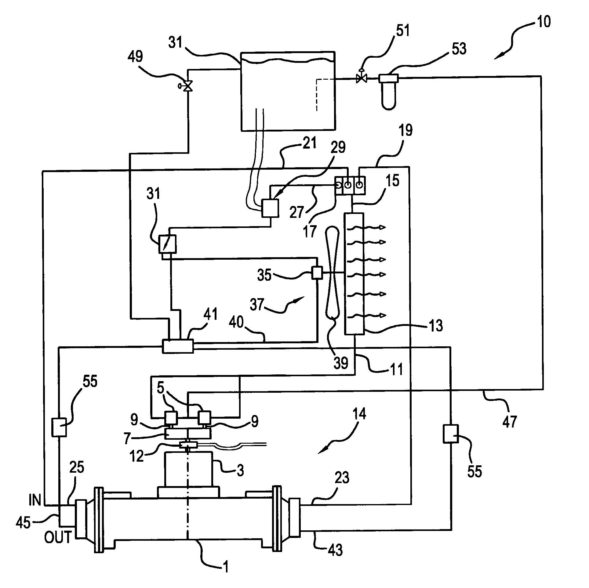
[0025]The present invention offers significant advantages in the field of heavy machinery that requires extensive braking due to the movement of heavy loads. Instead of requiring an additional engine for braking or complicated brake cooling systems, the present invention supplies a cooling fluid to the brakes of an axle assembly via the use of a system that relies on the axle components themselves for powering of the system.

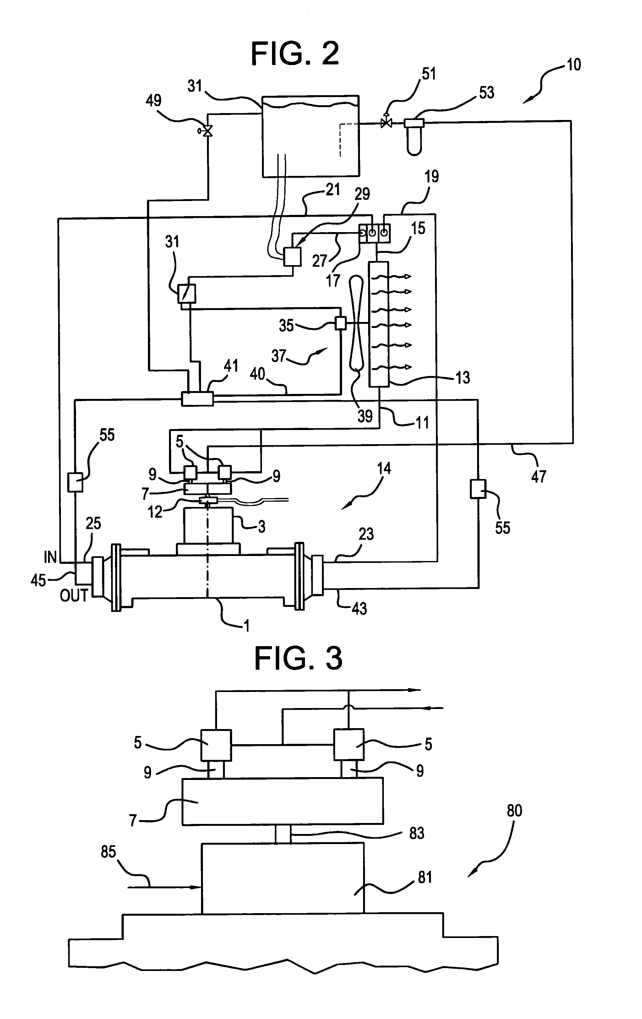
[0026]Referring now to FIG. 2, one embodiment of the inventive system is designated by the reference numeral 10. The system as shown is adapted for cooling of the brakes found in a Caterpillar 785 axle assembly 1 containing a transmission 3. While not shown, the axle / transmission assembly would be mounted on a trailer and would support trailer tires.

[0027]The system 10 employs a pair of hydraulic piston pumps 5, which are driven by a gear box drive 7, having two output shafts 9, each driving respective pumps 5.

[0028]The gear box drive 7 is powered by an output sh...


PUM


Abstract

An axle assembly that uses brakes that require cooling includes a brake cooling system that uses at least one hydraulic pump that supplies cooling oil to the brakes. Means for driving of the hydraulic pump using rotation of a component of the axle assembly such as a transmission or other mechanism is provided, thereby eliminating reliance on a towing vehicle. A heat exchanger cools the heated oil exiting from the brakes and recirculates the cooled oil back to the brakes for continued cooling.

Description

[0001]This application claims priority under 35 USC 119(e) based on application Ser. No. 60 / 426,486 filed on Nov. 15, 2002.FIELD OF THE INVENTION[0002]The present invention is directed to a brake cooling system, and, in particular, to a system that uses a transmission of the axle assembly to drive the cooling system.BACKGROUND ART[0003]In heavy duty mining or construction machinery, a number of different types of brake cooling systems for brakes in a vehicle axle assembly are often utilized. Some systems use the engine or power unit of the vehicle for brake cooling whereas others may use air to oil coolers or circulate a cooler fluid through the oil at the axle assembly itself.[0004]Another need for brake cooling systems is found in trailers designed to haul heavy duty mining equipment such as shovels and mine haulage trailers, e.g., bottom dump trailers, and the like. FIG. 1 shows a typical lowboy trailer 90 having a trailer bed 91 for supporting heavy machinery 92, a gooseneck 93,...

Claims


Application Information

Patent Timeline
Patent Type & Authority Patents(United States)
IPC IPC(8): F16D65/78B60T5/00F16D65/833F16D65/853
CPCF16D65/78F16D2065/787
Inventor SPIELMAN, HAROLD W
Owner GROUND FORCE MFG
Why Eureka
Try Eureka