Optical fiber code holding structure in which the number of the parts for the function of protecting the light from being directly viewed and the function of holding the optical fiber code is reduced and the connecting work of an optical connector is easily performed

Inactive Publication Date: 2006-05-02
NEC CORP
View PDF20 Cites 1 Cited by
  • Summary
  • Abstract
  • Description
  • Claims
  • Application Information

AI Technical Summary

Benefits of technology

[0026]The present invention is accomplished in view of the above mentioned problems of the conventional techniques. Therefore, an object of the present invention is to provide an optical fiber code holding structure and an optical fiber code holding member, in which a function of protecting a light from being directly viewed is added to an optical fiber code holding member to thereby reduce the number of the parts necessary for the function of protecting the light from being directly viewed and the function of holding the optical fiber code, and the structure can be simplified to thereby improve the economical efficiency and easily carry out the connecting work of an optical connector.

Problems solved by technology

This results in a problem that the manufacturing cost can not be entirely reduced.
Thus, they are the expensive parts.

Method used


Image

  • Optical fiber code holding structure in which the number of the parts for the function of protecting the light from being directly viewed and the function of holding the optical fiber code is reduced and the connecting work of an optical connector is easily performed
  • Optical fiber code holding structure in which the number of the parts for the function of protecting the light from being directly viewed and the function of holding the optical fiber code is reduced and the connecting work of an optical connector is easily performed
  • Optical fiber code holding structure in which the number of the parts for the function of protecting the light from being directly viewed and the function of holding the optical fiber code is reduced and the connecting work of an optical connector is easily performed

Examples


first embodiment

[First Embodiment of Optical Fiber Code Holding Structure]

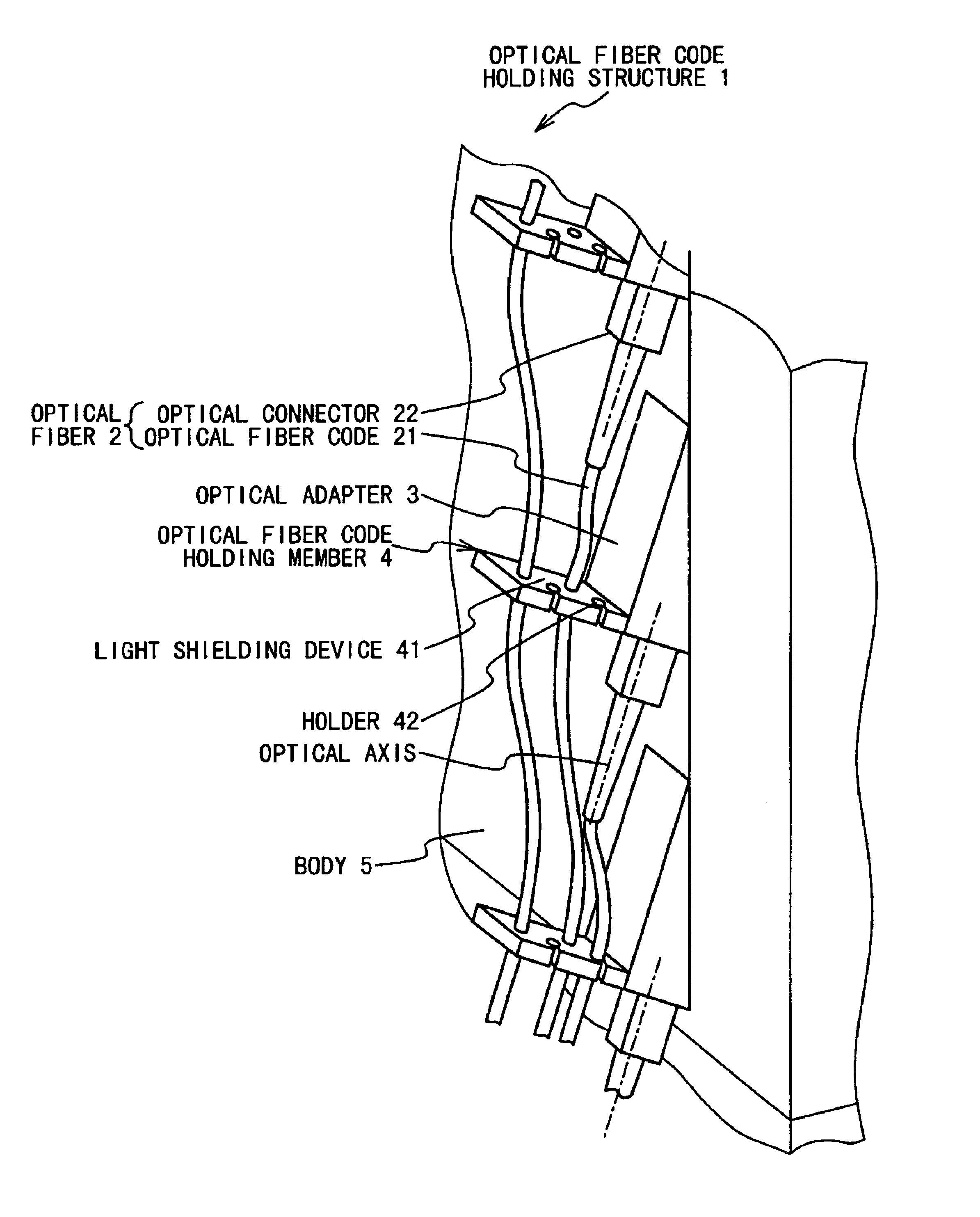
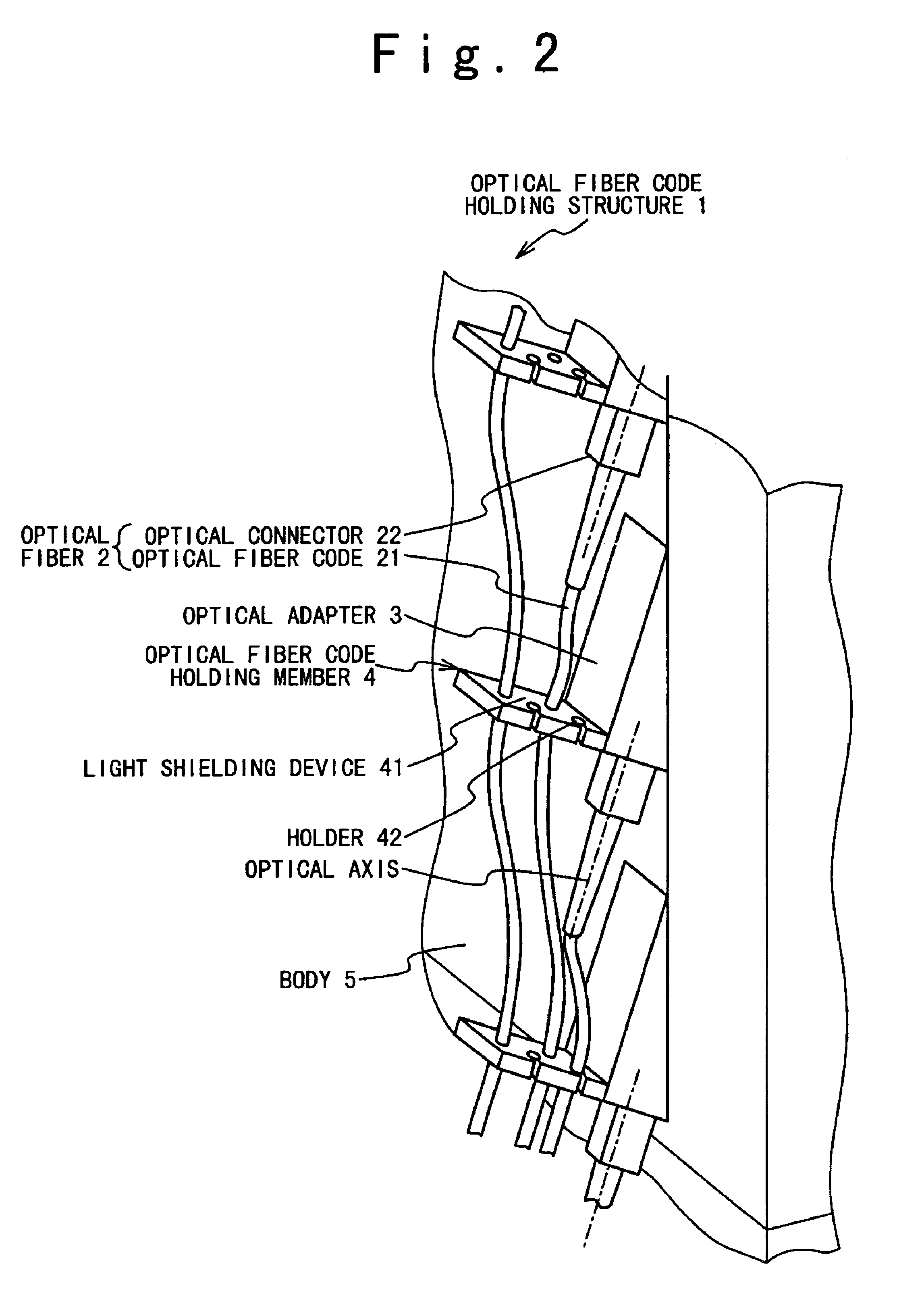
[0071]FIG. 2 shows a schematic perspective view illustrating the first embodiment of the optical fiber code holding structure according to the present invention, and FIG. 3 shows a schematic side view illustrating the optical fiber code holding structure according to this embodiment.

[0072]By the way, in FIG. 3, a part of an optical fiber code 21 is omitted and illustrated for the purpose of easy understanding.

[0073]As shown in FIGS. 2, 3, an optical fiber code holding structure 1 in this embodiment is provided with: optical fibers 2 in which optical connectors 22 are attached to ends of the optical fiber codes 21; optical adapters 3 to which the optical connectors 22 are connected; light shielding devices 41 for shielding output lights emitted from the optical adapters 3; and an optical fiber code holding member 4 having a holder 42 for holding the optical fiber code.

[0074]Here, the optical adapters 3 are arrayed in a directi...

second embodiment

[Second Embodiment of Optical Fiber Code Holding Structure]

[0118]A second embodiment of an optical fiber code holding structure according to the present invention will be described below with reference to FIG. 5.

[0119]FIG. 5 shows a schematic top view of an optical fiber code holding member to describe the second embodiment of the optical fiber code holding structure according to the present invention.

[0120]In FIG. 5, the optical fiber code holding structure in this embodiment is configured such that a light shielding device 41a of an optical fiber code holding member 4a is rotated.

[0121]The optical fiber code holding member 4a is composed of a square light shielding device 41a rotatably placed on an upper portion; holders 42a formed on both sides of the light shielding device 41a; and a spring 425 for pushing the light shielding device 41a to the same flat plane position as the holder 42a.

[0122]Also, the optical fiber code holding structure in this embodiment is configured such th...


PUM


Abstract

An optical fiber code holding structure, includes: an optical adapter and an optical fiber code holding member. An optical connector of an optical fiber is connected to an optical adapter. The optical connector is attached to an end of an optical fiber code of the optical fiber. The optical fiber code holding member has a light shielding device shielding lights emitted from the optical adapter and a holding device holding the optical fiber code.

Description

BACKGROUND OF THE INVENTION[0001]1. Field of the Invention[0002]The present invention relates to an optical fiber code holding structure and an optical fiber code holding member. More particularly, the present invention relates to an optical fiber code holding structure and an optical fiber code holding member for shielding lights emitted from an optical adapter and thereby protecting the emitted lights from being directly viewed.[0003]2. Description of the Related Art[0004]Conventionally, the structure of holding an optical fiber code connected to an optical adapter uses a wire saddle as a member for holding the optical fiber code. This wire saddle is designed so as to have only a function of holding the optical fiber code.(Conventional Example)[0005]The conventional typical optical fiber code holding structure will be described below with reference to the drawing.[0006]FIG. 1 is a schematic perspective view illustrating the conventional typical optical fiber code holding structure...

Claims


Application Information

Patent Timeline
IPC IPC(8): H01J9/06H01J9/10H01J9/16H01J9/46H05B33/10G02B6/36G02B6/00G02B6/38G02B6/44
CPCG02B6/4471G02B6/3825G02B6/3616G02B6/3636G02B6/3644
Inventor FUJIOKA, SHINTAROOOTANI, HIROSHINAKAMURA, YOSHINORIMEGURO, HISAKAZU
Owner NEC CORP
Why Eureka
Try Eureka