Low torque twist-on wire connector

a twist-on wire connector, low-torque technology, applied in the direction of connecting end caps, connecting contact member materials, conductor screwing into other, etc., can solve the problems of reducing the integrity of the connection between the wires in the twist-on wire connector, time-consuming prior art process, etc., to achieve the effect of reducing the rate of torsonial resistance, reducing the frictional resistance to the rotation of the wire, and low resistan

Inactive Publication Date: 2006-05-02
KING JR LLOYD H
View PDF6 Cites 4 Cited by
  • Summary
  • Abstract
  • Description
  • Claims
  • Application Information

AI Technical Summary

Benefits of technology

[0010]Briefly, the present invention is an improved twist-on wire connector that permits the user to form the junction ends of wire leads into a low resistance electrical connection with the twist-on wire connector including a self adhering lubricant located along a portion of the interior of the twist-on wire connector. The wires are drawn into the housing by a spiral thread through the twisting action of the wires with respect to housing. As the wires are drawn into the spiral thread, the frictional resistance to the rotation of the wires increases until the wires can no longer be hand twisted into the wire connector. Once the wires are drawn into contact with the lubricant the torque resistance, which is a result of frictional resistance between the wires and the spiral thread, decreases while th

Problems solved by technology

The prior art process is time consuming because it involves two separate steps as well as the nuisance of having separate potting compounds and containers to hold the potting compound.
Under certain dynamic conditions, such as vibration and shock, or large temp

Method used


Image

  • Low torque twist-on wire connector
  • Low torque twist-on wire connector
  • Low torque twist-on wire connector

Examples


Embodiment Construction

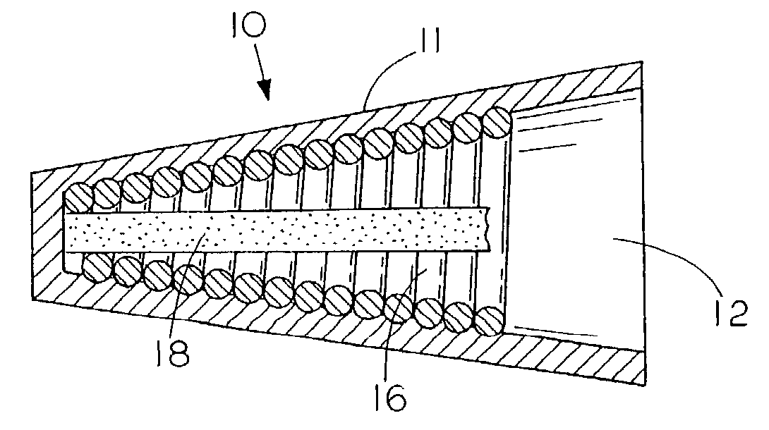
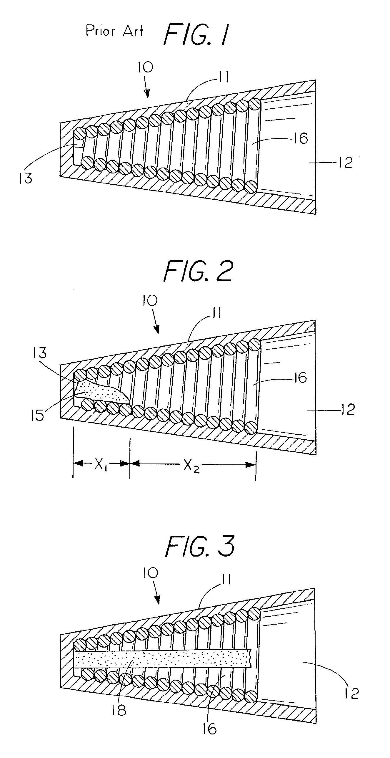
[0019]Referring to FIG. 1, reference numeral 10 generally identifies a conventional twist-on wire connector. Wire connector 10 includes an electrical insulating housing 11 having an open end 12 and a closed end 13 with the diameter of open end 12 being larger than the diameter of closed end 13. A spiral thread 16 extends axially inwardly in housing 11. The diameter of spiral thread 16 proximate open end 12 of housing 11 is larger than the diameter of spiral thread 16 proximate closed end 13 of housing 11 so that wires are squeezed into tighter contact with each other as the wires are twisted into the spiral thread. While the embodiment shows that the spiral thread is a metal spring it is envisioned that the spiral thread could be integrally formed within the housing of the twist-on wire connector.

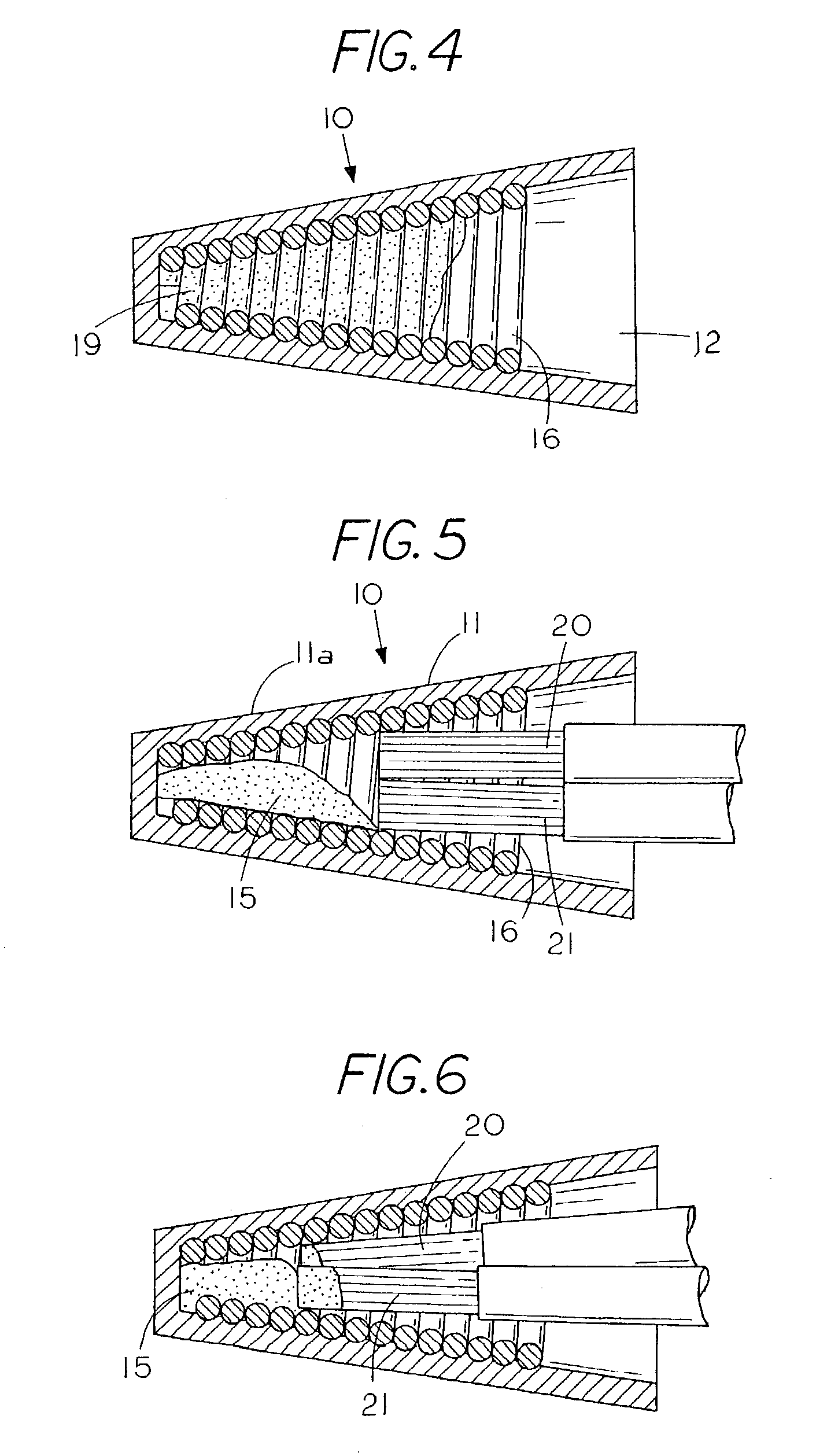
[0020]FIG. 2 shows an embodiment of the present invention having a self-adhering lubricant 15 positioned at the closed end 13 of connector 10. The self-adhering lubricant 15 extends an axia...


PUM

PropertyMeasurementUnit
Temperatureaaaaaaaaaa
Diameteraaaaaaaaaa
Electrical resistanceaaaaaaaaaa

Abstract

A method of making a two-stage twist-on wire connector comprising the steps of forming a housing; placing a spiral thread on an interior of the housing with the spiral thread having an open end and a closed end with a diameter of the open end of the spiral thread larger than the diameter of the closed end, the spiral thread diametrically converging in an axial direction toward the closed end; inserting a lubricant into the closed end of the spiral thread; inserting a plurality of wire ends to be splice into the open end of the spiral thread; twisting the plurality of wires and the wire connector to draw the plurality of wire ends proximate the closed end of the spiral thread to improve the continuity of said the splice; and applying the lubricant to the spiral threads by the twisting engagement of the wires with respect to the spiral threads.

Description

CROSS REFERENCE TO RELATED APPLICATIONS[0001]This application claims is a continuation application of U.S. application Ser. No. 09 / 987,780, filed on Nov. 16, 2001 now U.S. Pat. No. 6,570,094, claiming priority from provisional application titled LOW TORQUE TWIST-ON WIRE CONNECTOR U.S. Ser. No. 60 / 251,111, filed Dec. 5, 2000.FIELD OF THE INVENTION[0002]This invention relates generally to wire connectors, and more specifically, to a twist-on wire connector having a lubricant thereon to reduce the torque required to set the electrical wires in the wire connector and at the same ensure that the electrical wires are securely engaged so that normal thermal expansion and contraction or shock and vibration conditions will not cause the wires to loosen in the connector.STATEMENT REGARDING FEDERALLY SPONSORED RESEARCH OR DEVELOPMENT[0003]NoneREFERENCE TO A MICROFICHE APPENDIX[0004]NoneBACKGROUND OF THE INVENTION[0005]The concept of wire connectors for connecting the junction of two or more wi...

Claims


Application Information

Patent Timeline
IPC IPC(8): H01R4/22C10M107/38C10M107/50C10N40/32C10N50/08H01R4/56H01R4/58H01R43/00H01R43/02
CPCH01R4/22
Inventor KING, JR., LLOYD H.
Owner KING JR LLOYD H
Why Eureka
Try Eureka