Beverage dispensing apparatus

a technology for beverage dispensers and beverage dispensers, which is applied in the direction of liquid handling, packaged goods, instruments, etc., can solve the problems of excessive foam, unsatisfactory consumer experience, and excessive foam, so as to reduce the amount of foaming that occurs when beer is dispensed at fast rates, reduce the cross-sectional area, and the effect of less turbulen

Inactive Publication Date: 2006-05-09
LAMINAR TECH
View PDF38 Cites 42 Cited by
  • Summary
  • Abstract
  • Description
  • Claims
  • Application Information

AI Technical Summary

Benefits of technology

[0012]The present invention is directed to a beverage dispensing device for dispensing pressurized beverages at a flow rate substantially higher than prior mechanical tap apparatus without producing excessive foaming. It can be implemented as a purely mechanical device so as to keep manufacturing and maintenance costs low. In addition, the present invention can be implemented without the use of reservoirs at or near the point of dispensing, thus facilitating cleaning and retrofitting to existing bar tops.
[0013]In a preferred embodiment, the present invention comprises a beverage dispensing apparatus for dispensing a pressurized beverage comprising a nozzle through which the pressurized beverage at least initially exits at atmospheric conditions having an internal passageway, a liquid receiving end adapted to attach as the end element of a pressurized beverage dispensing system, and a liquid dispensing end that dispenses the pressurized beverage at least initially to atmospheric conditions, wherein the cross-sectional area of the internal passageway of the nozzle decreases from the liquid receiving end to the liquid dispensing end. The nozzle is adapted at its liquid receiving end to removably and sealingly fit to the end of a conventional carbonated beverage faucet.
[0014]In another embodiment, the present invention comprises an upward extending neck, a streamlined valve assembly and a downward extending nozzle assembly. The overall shape and size of the device permits a range of containers to be filled from the bottom. Additionally, the nozzle assembly contains a streamlined flow redirecting component that serves to generally radially disperse liquid flow. Thus, the amount of foaming that occurs when beer is dispensed at fast rates is desirably reduced.
[0015]In one embodiment, the horizontal cross-sectional area of the nozzle gradually decreases from the top of the nozzle to the bottom or liquid dispensing end of the nozzle. Preferably, the profile of this decreasing cross-sectional area is consistent with that of a liquid stream falling under the force of gravity in the absence of such a nozzle. A nozzle with this shape ensures that liquid flowing through it remains in substantially continuous contact with the interior wall of the nozzle. In this way, air from the liquid dispensing end of the nozzle is prevented from bubbling up into the nozzle. Additionally, the viscous forces acting between the nozzle interior wall and the liquid flowing through the nozzle serve to counteract the acceleration experienced by the liquid in the nozzle due to gravitational forces.
[0016]In another embodiment of the invention, flow-straightening elements are added to the nozzle which may serve to make the flow of liquid through the nozzle less turbulent. Such elements also increase the amount of surface area across which decelerating viscous forces can take effect.
[0017]In another embodiment of the invention, the device is able to selectively dispense beer at two different flow rates. In such an embodiment a pressure-reducing element is integrated into the device along with a multi-way valve that selectively routes liquid through the pressure-reducing element. When the valve is positioned such that liquid first flows through the pressure reducer before entering the rapid beverage dispensing device, liquid is dispensed at a reduced rate, preferably the optimal rate of conventional beer dispensing faucets. When the valve is positioned such that liquid bypasses the pressure reducer, the rapid beverage dispensing device functions at its faster flow rate.

Problems solved by technology

Due to the complex chemical makeup of beer, foam tends to form when this dissolved CO2 comes out of solution.
One cause of such foaming is simply the pressure differential between CO2 dissolved in the beer and CO2 present in the ambient atmosphere; CO2 will naturally be released from the beer when the beer is exposed to the atmosphere.
Another cause of such foaming is the turbulent nature by which beer is dispensed from conventional faucets; even when dispensed carefully, beer splashes onto the walls and bottom of the container and foam results.
On the other hand, too much foam is undesirable to the consumer and the beverage vendor.
Since foam fills up a container with CO2 instead of with liquid beer, excessive amounts of foam leave the consumer dissatisfied, often to the point of requesting a new container be served.
They can partially fill a container, wait for the foam to dissipate and then add additional beer, a time-consuming process.
Alternatively, they can pour out excess foam as they are filling the container, wasting beer in the process.
One drawback with these systems is that they typically employ elaborate electronic control mechanisms, making them expensive to manufacture and maintain.
Additionally, some of these systems employ the use of a reservoir near the point of the faucet making the devices large and difficult to clean.
Moreover, the retrofit of such devices onto existing bar tops can be difficult and expensive.

Method used


Image

  • Beverage dispensing apparatus
  • Beverage dispensing apparatus
  • Beverage dispensing apparatus

Examples


Embodiment Construction

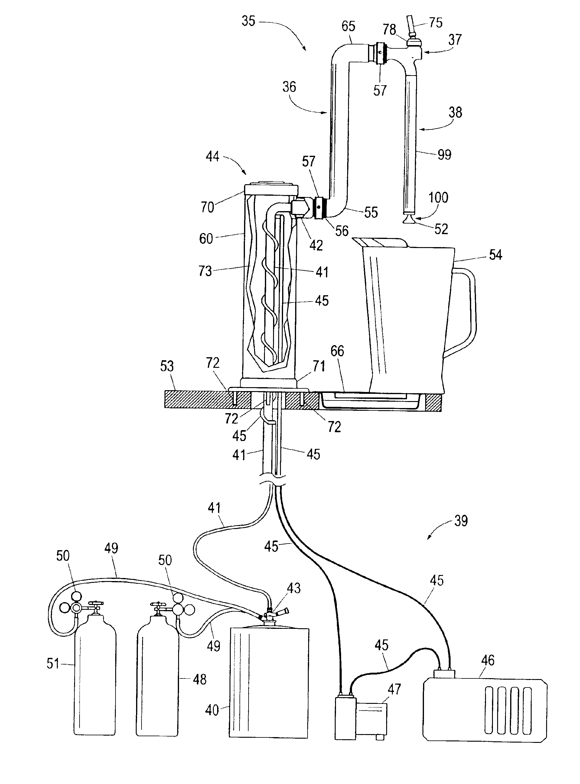
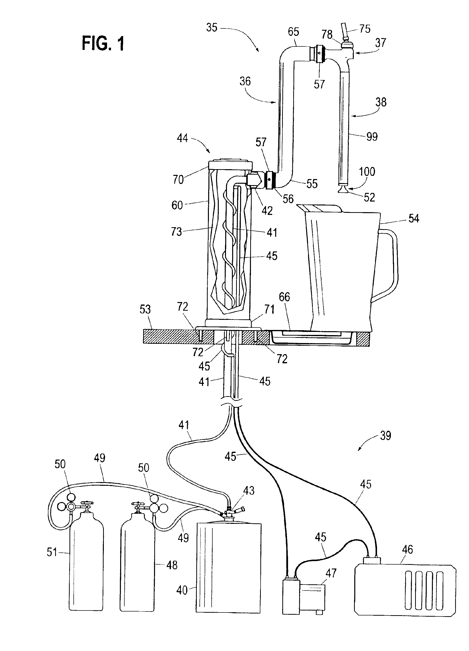
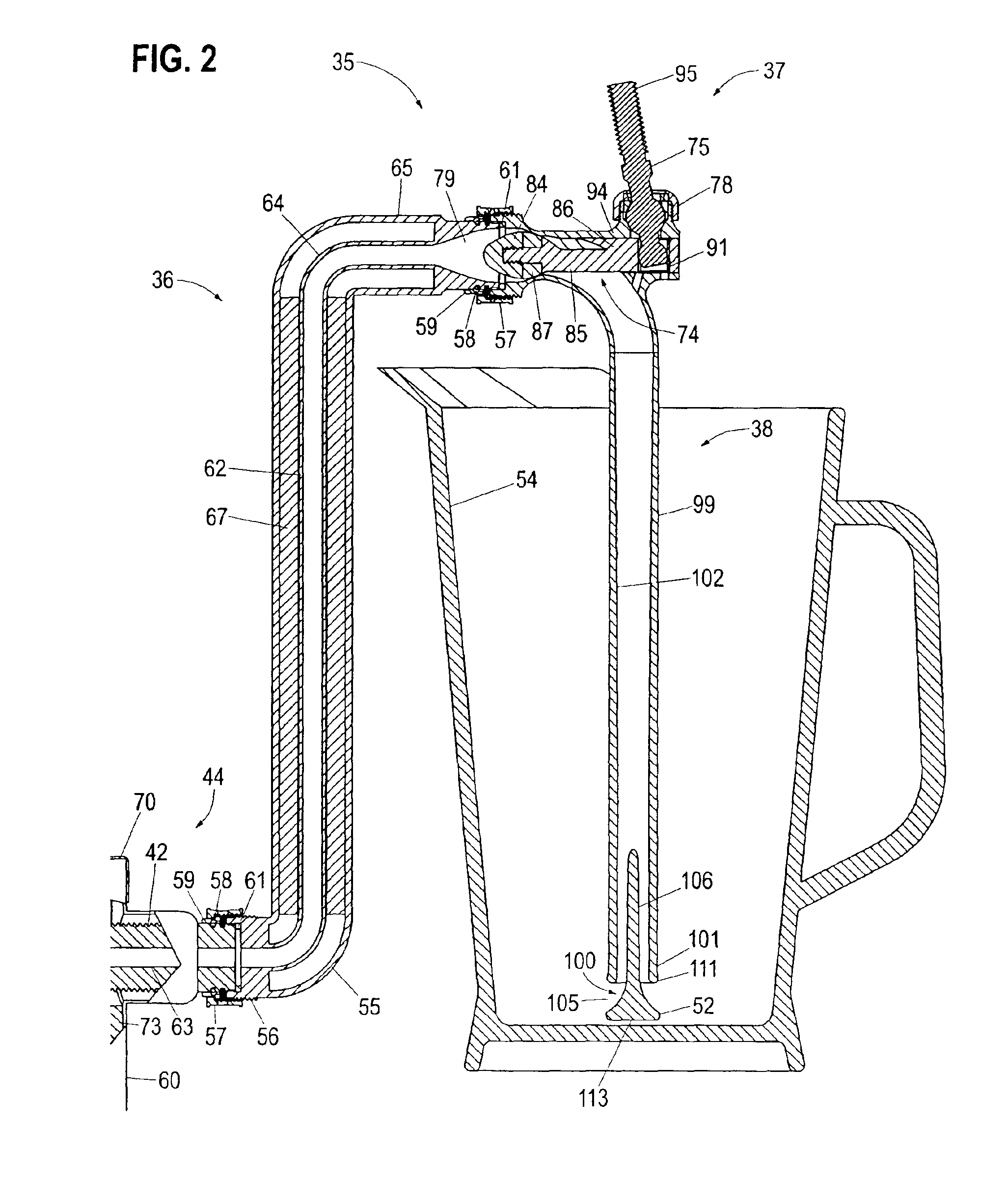
[0053]As shown in FIG. 1, the rapid beverage dispensing device 35 comprises a neck assembly 36, a valve assembly 37, and a downward-extending nozzle assembly 38. In a preferred embodiment, neck assembly 36 is substantially vertical. The rapid beverage dispensing device 35 is designed to attach to a conventional pressurized beverage dispensing system, such as a beer dispensing system 39 that includes a beer keg 40 or similar beverage-containing reservoir and beverage tubing 41 for conveying a beverage from a container or beer keg 40 to the rapid beverage dispensing device 35. A shank 42 connects the rapid beverage dispensing device 35 to beverage tubing 41. Keg tapping device 43 connects beverage tubing 41 to beer keg 40. Draft dispensing tower 44 supports shank 42.

[0054]Beer produced by most major manufacturers in the United States is formulated to be stored and served optimally at approximately 38 degrees Fahrenheit (3.3 degrees Celsius). If the beer is warmer than this optimal tem...


PUM

PropertyMeasurementUnit
temperatureaaaaaaaaaa

Abstract

A removable nozzle for attachment to a conventional faucet of a beverage dispensing device to permit the dispensing of a pressurized beverages at a high flow rate without producing excessive foaming comprising a streamlined valve assembly and a downward extending nozzle assembly which permits a range of containers to be filled from the bottom.

Description

[0001]This application is a continuation-in-part of U.S. patent application Ser. No. 10 / 388,907 filed on Mar. 13, 2003.[0002]The present invention relates to a nozzle for dispensing carbonated or pressurized beverages, and more specifically to a removable nozzle for adapting a conventional carbonated beverage faucet to dispense carbonated or pressurized beverages at high flow rates with minimal foaming.BACKGROUND OF THE INVENTION[0003]Pressurized beverages, such as beer, are produced in a manner that the beverage contains a certain amount of dissolved gas, typically carbon dioxide (CO2). While a certain amount of dissolved CO2 occurs naturally in the beer brewing and fermentation process, most large commercial breweries dissolve additional CO2 into their product. Adding additional CO2 serves two main purposes for the commercial breweries. First, from a quality control standpoint, all the beer produced can be modified to contain the same amount of CO2. Second, the additional CO2 give...

Claims


Application Information

Patent Timeline
Patent Type & Authority Patents(United States)
IPC IPC(8): B67C3/26B05B1/02B05B1/26B05B1/30B67D1/00B67D1/08B67D1/14B67D7/42F16K1/12
CPCB05B1/265B05B1/3013B67D1/0865B67D1/0872B67D1/127F16K1/12B67D1/1422B67D1/1455B67D1/1466B67D1/14B67D2210/00052
Inventor YOUNKLE, MATTHEW C.
Owner LAMINAR TECH
Why Eureka
Try Eureka