Method for data communication between a vehicle and a remote terminal

a technology for remote terminals and vehicles, applied in the field of methods, can solve problems such as undesirable inefficiency, cumbersome techniques, and limited information capacity, and increase the chances of error and omission by human links in the accounting process

Inactive Publication Date: 2006-05-09
VES TEK +3
View PDF12 Cites 63 Cited by
  • Summary
  • Abstract
  • Description
  • Claims
  • Application Information

AI Technical Summary

Benefits of technology

[0018]With the foregoing in mind, the present invention advantageously provides an apparatus and methods of data communication between a vehicle and a remote data communication terminal so that various operating characteristics of the vehicle can be monitor or observed. The present invention also advantageously provides an apparatus and methods of data communication for discretely and compactly communicating data between a vehicle and a remote data communication terminal. The present invention additionally provides an apparatus and method of data communication which is readily adapted to existing vehicle data communication technology and does not require either extensive retrofitting or extensive and expensive additions to existing vehicle data communication technology. The present invention further advantageously provides an apparatus and methods of data communication so that when the apparatus is mounted to a vehicle a third party would not readily recognize that the vehicle is equipped for data communications from the vehicle to a remote data communications terminal. The present invention still further advantageously provides vehicle identification systems and methods for identifying vehicles such as tractor / trailer rigs and components thereof which are accurate under low light and other visibility-obscuring conditions, which are resistant to electromagnetic interference, and which may identify a tractor / trailer rig and components thereof when the tractor / trailer rig is in motion.

Problems solved by technology

Techniques have been developed for tracking rigs and their components as the rigs travel between cargo terminals, delivery points, weigh stations, and the like, but these techniques generally are cumbersome and limited in effectiveness and information capacity.
These numbers typically are read and recorded by human operators—a time-consuming process which represents an undesirable inefficiency in an industry in which time is usually critical.
Besides being inefficient, the human link in the accounting process increases the chances for error and omission, particularly under conditions of darkness or obscured visibility.
In addition, a serial or other identification number may fail to convey a complete identity.
Failures in the link of the accounting chain may result in erroneous component and cargo designations leading to confused shipments and misplaced components.
Bar-code or magnetic-stripe identification systems reduce the human error involved in the use of numbering systems, but have drawbacks of their own.
Because of the need to make codes or magnetic stripes accessible to readers, codes and stripes are typically affixed to surfaces of the rig which are exposed to wind, rain, salt, and other environmental contaminants which may render the codes or stripes unreadable.
In addition, reading a bar code or magnetic stripe typically requires close proximity between the reader and the code or stripe, generally precluding remote reading or reading while the rig is in motion.
Moreover, bar codes and magnetic stripes have a relatively limited informational capacity.
Much of this previous slow, or lack of, development and advances could be attributed, for example, to the lack of governmental or other authoritative initiatives which would have otherwise required systems to be installed on these heavy duty vehicles to include sophisticated electronics and data communications.
Although only recently have advances been made with data communications in the heavy duty vehicle industries, many of the advances require extensive retrofitting or extensive additions to the heavy duty vehicle.
Accordingly, many vehicle owners have been hesitant to adopt and purchase sophisticated electronics and data communications because of the expense and uncertainty with the advances in the technology.
Although these conventional systems are effective for receiving data from and transmitting data to the data bus of the vehicle, these interrogation devices require physical connection to the vehicle, which may not be desirable in situations where the vehicle is either in transit or is remote from the interrogation device requesting data input.
Although remote, wireless communication with the computer system of a vehicle is typically desired, the physical limitations of the communication infrastructure of most vehicles hinder the move to wireless communication.
Communication on the data bus of these vehicles may be problematic due to the nature of the J1708 and J1939 standards.
These systems, however, still have extensive limitations.

Method used


Image

  • Method for data communication between a vehicle and a remote terminal
  • Method for data communication between a vehicle and a remote terminal
  • Method for data communication between a vehicle and a remote terminal

Examples


first embodiment

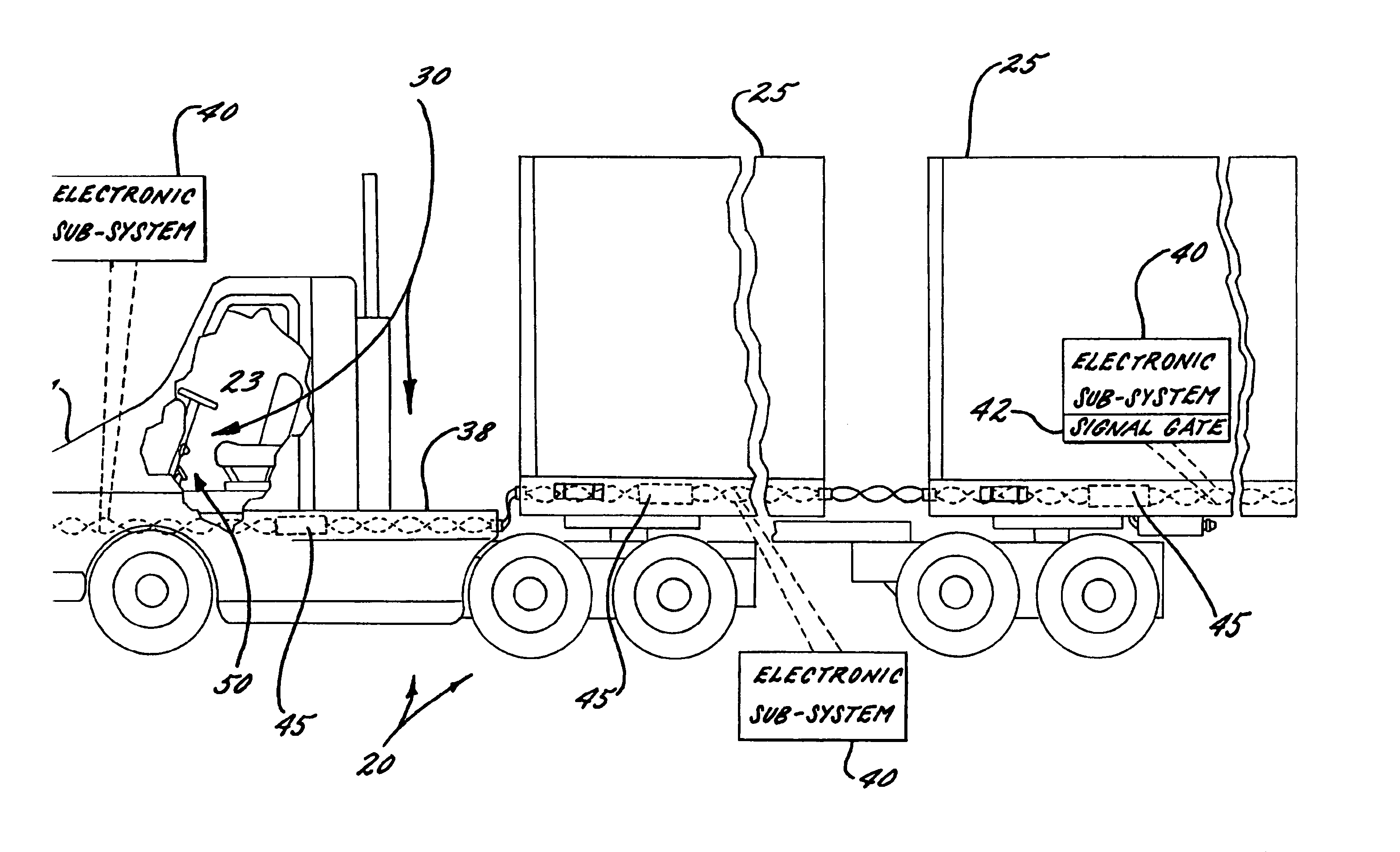
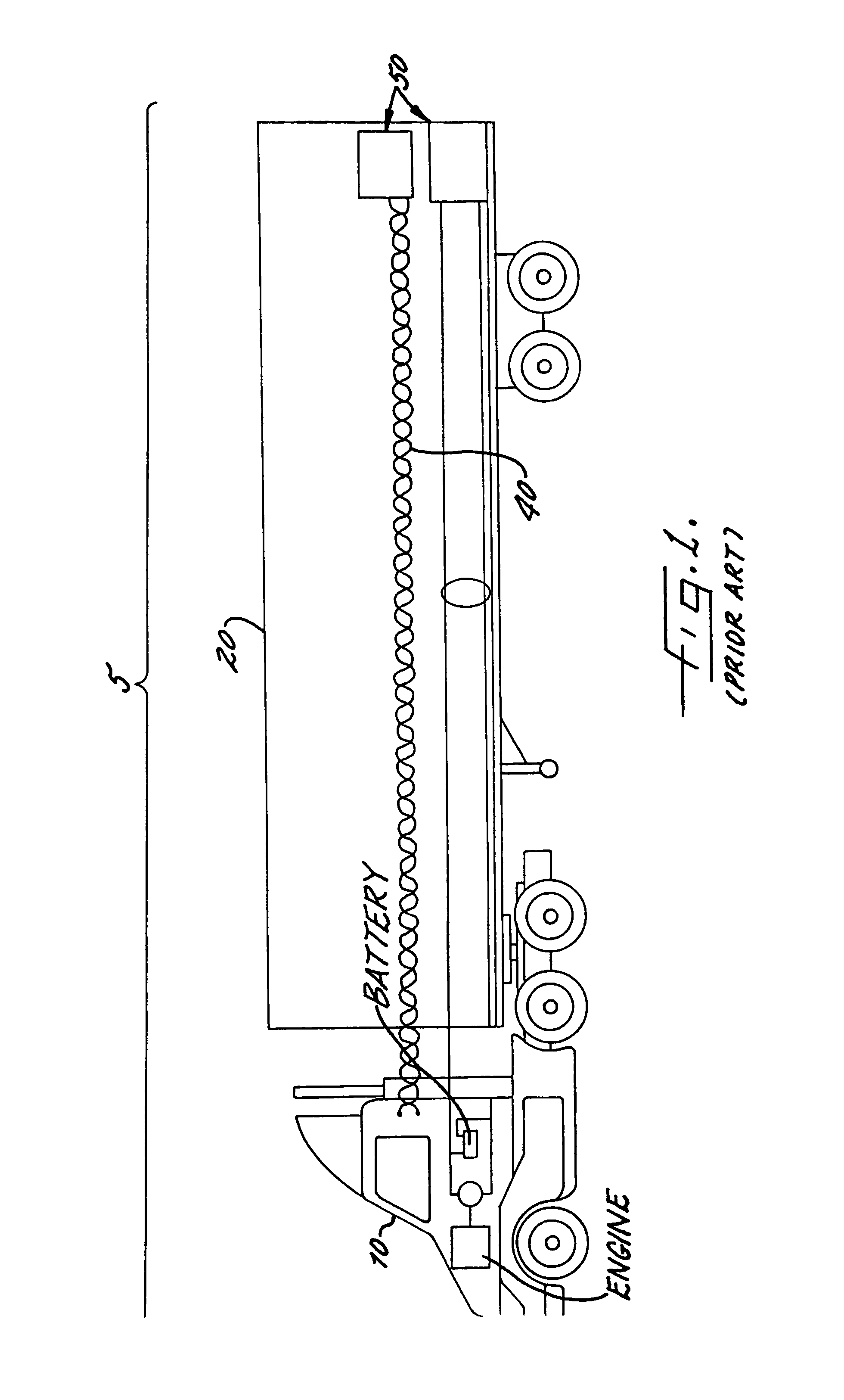
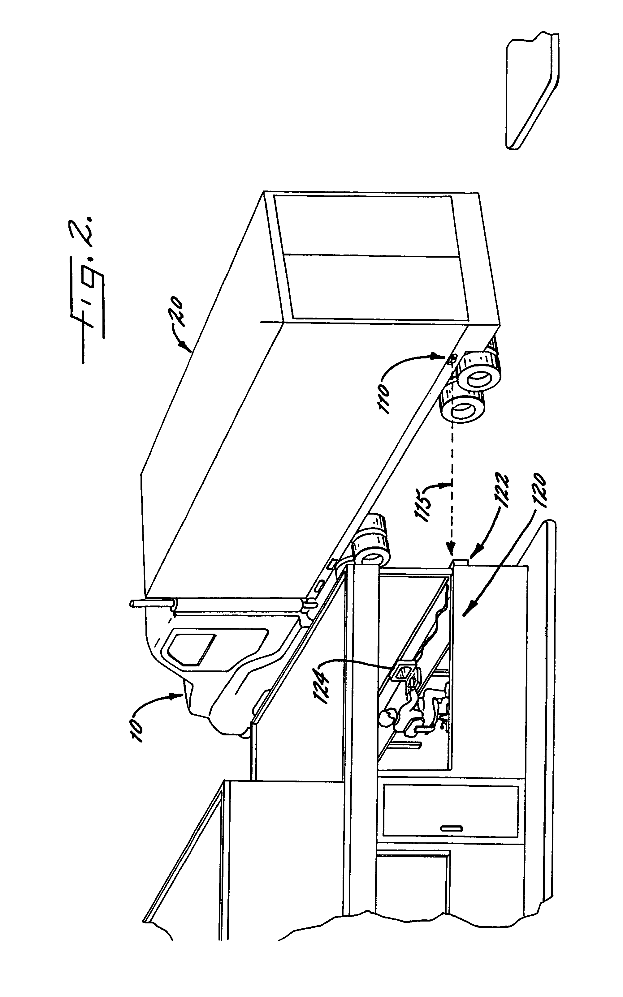
[0089]FIGS. 10–12 illustrate an apparatus 30 for data communications associated with a heavy duty vehicle 20, namely a tractor / trailer combination or tractor / trailer truck, according to the present invention. As understood by those skilled in the art, the tractor / trailer combination preferably includes a tractor 21 connected to a trailer 25 for pulling the trailer 25. The tractor 21 and trailer 25 include respective frames and coupling means for coupling the trailer 25 to the tractor 21. In addition, the tractor 21 includes an engine, such as a diesel engine or other motor, for moving the tractor 21 to thereby pull the trailer 25. It will also be understood by those skilled in the art that other types of heavy duty vehicles, such as a recreational vehicle, agricultural tractors or other heavy duty vehicles used in association with agricultural uses, can also be used according to the present invention.

[0090]The data communications apparatus 30 preferably includes at least one electro...

second embodiment

[0104]As perhaps best illustrated in FIGS. 15–16, in the transceiver housing 34′, the transceiver housing 34′ can advantageously be a vehicle light housing mounted to the heavy duty vehicle 20 for housing a vehicle light. The vehicle light housing, for example, can advantageously be a side-marker light housing mounted to the trailer 25 of a truck so that a third party would not readily recognize that the truck is equipped with the data communications apparatus 30.

[0105]A transceiver 35 is preferably positioned within the transceiver housing 34, 34′ and connected to the vehicle data communications protocol converting means 33 for transmitting the second data communications protocol from the heavy duty vehicle 20 and receiving the data communications protocol from a remote data communications terminal 60. For infrared data communications, for example, the transceiver 35 (see also FIG. 13) preferably includes a plurality of infrared light emitter or light emitting diodes, a plurality o...


PUM


Abstract

An apparatus and methods are provided for data communications associated with a vehicle. The apparatus preferably includes at least one electronic subsystem associated with the vehicle and a plurality of electrical conductors connected to the at least one electronic subsystem and associated with the vehicle. A vehicle data communications protocol converter is preferably connected to the plurality of electrical conductors for converting a first data communications protocol associated with data communications along the plurality of electrical conductors to a second data communications protocol such as a local-area infrared or an RF data communications protocol. The apparatus also preferably includes a transceiver connected to the data communications protocol converter for transmitting the second data communications protocol from the vehicle and receiving the data communications protocol from a remote data communications terminal or another portion of the vehicle.

Description

FIELD OF THE INVENTION[0001]The present invention relates to the field of vehicle data communications and, more particularly, to data communications from a vehicle to a remote location.BACKGROUND OF THE INVENTION[0002]Data communications within vehicles has developed extensively over the years. The truck industry, for example, has for many years used tractor / trailer combinations to transport cargo over the roadways to intended destinations. As shown in FIG. 1, an ensemble of components, including a tractor 10 and a trailer 20 mechanically couple together so that the tractor can pull the trailer, from a vehicle 5, often referred to as a “rig,” which can transport cargo in an efficient and cost effective manner. Various links between the tractor and the trailer provide vehicle subsystems with power and / or control signals to operate. Hydraulic, pneumatic, electrical, and other subsystems on the rig have associated electrical conductors and pneumatic lines running therebetween so these ...

Claims


Application Information

Patent Timeline
Patent Type & Authority Patents(United States)
IPC IPC(8): G08B21/00G07C5/00G07C5/08G08G1/017H04L12/28H04L12/56
CPCG07C5/008G07C5/085H04B10/22G08G1/017H04W4/18H04B10/1143
Inventor LESESKY, ALANWEANT, BOBBY RAY
Owner VES TEK
Why Eureka
Try Eureka