Alloy type thermal fuse and wire member for a thermal fuse element

a technology of alloy type thermal fuse and wire member, which is applied in the direction of manufacturing tools, welding/cutting media/materials, and manufacturing tools, etc., can solve the problems of local and sudden temperature rise, physical destruction, and intense scattering of molten alloy or charred fluxes, so as to reduce the specific resistance of the fuse element and increase the capacity of the alloy type thermal fuse. , the effect of high drawability

Inactive Publication Date: 2006-05-09
UCHIHASHI ESTEC
View PDF31 Cites 23 Cited by
  • Summary
  • Abstract
  • Description
  • Claims
  • Application Information

AI Technical Summary

Benefits of technology

[0030]According to the wire member for a thermal fuse element of the invention, it is possible to provide an alloy type thermal fuse in which a ternary Sn—In—Bi alloy containing no metal harmful to the ecological system is used, the operating temperature belongs to the range of 130 to 170° C., destruction does not occur even when the fuse is operated under an overload application, and the insulation stability after an operation can be sufficiently ensured. Because of the low specific resistance of the fuse element, the alloy type thermal fuse can be operated at a predetermined operating temperature even under a large load current, and the capacity of the alloy type thermal fuse can be increased. Since the wire member for a thermal fuse element has high drawability, the fuse element can be easily thinned. Therefore, the wire member is suitable for miniaturization and thinning of a thermal fuse.
[0031]In embodiment 2, particularly, the drawability of the fuse element can be further improved, and the specific resistance can be further lowered, whereby the miniaturization and thinning of the alloy type thermal fuse can be more enhanced. Even in the case where a thermal fuse is configured by bonding a fuse element to a member which may substantially affect the characteristics, a normal operation can be assured without impairing the function of the fuse element.
[0032]In the alloy type thermal fuses of embodiments 9 and 10, since the element temperature at an operation is set to be very lower than the liquidus temperature of the element, the division of the element can be performed in a wide solid-liquid coexisting region, the occurrence of an arc immediately after an operation can be satisfactorily suppressed, a local and sudden temperature rise can be sufficiently prevented from occurring, pressure rise caused by vaporization of the flux due to the temperature rise, and charring of the flux can be suppressed, and the insulation distance can be sufficiently ensured. As a result, also in the case of an alloy other than the ternary Sn—In—Bi alloy, it is possible to assure excellent overload characteristic and dielectric breakdown characteristic after an operation.

Problems solved by technology

However, the former two fuses contain metals harmful to the ecological system such as lead and cadmium, and hence are inadequate under the recent strict environmental regulations.
When an arc is generated, a local and sudden temperature rise occurs.
In addition to the above, also the high surface tension causes the molten alloy or the charred flux to be intensely scattered as a result of an energizing operation.
Therefore, physical destruction such as generation of cracks due to a local and sudden temperature rise, a rise of the internal pressure, or reconduction between charred flux portions easily occurs during an operation.
Moreover, the insulation distance is shortened by the scattered alloy or the charred flux, so that dielectric breakdown is easily caused by reconduction when a voltage is applied after an operation.
Furthermore, the alloy structure is slightly weak and has poor ductility.
Therefore, the alloy is hardly thinned to, for example, 200 μmφ, and hence is not meet the requirement of a thinned thermal fuse.
However, all the proposed fuses have an operating temperature which is lower than 130° C., and cannot satisfy the requirement that the operating temperature is 130 to 170° C.
With respect to the range of higher than 135° C. and not higher than 170° C., however, the fuse cannot satisfy the requirement that the operating temperature is 130 to 170° C.

Method used


Image

  • Alloy type thermal fuse and wire member for a thermal fuse element
  • Alloy type thermal fuse and wire member for a thermal fuse element
  • Alloy type thermal fuse and wire member for a thermal fuse element

Examples


example 1

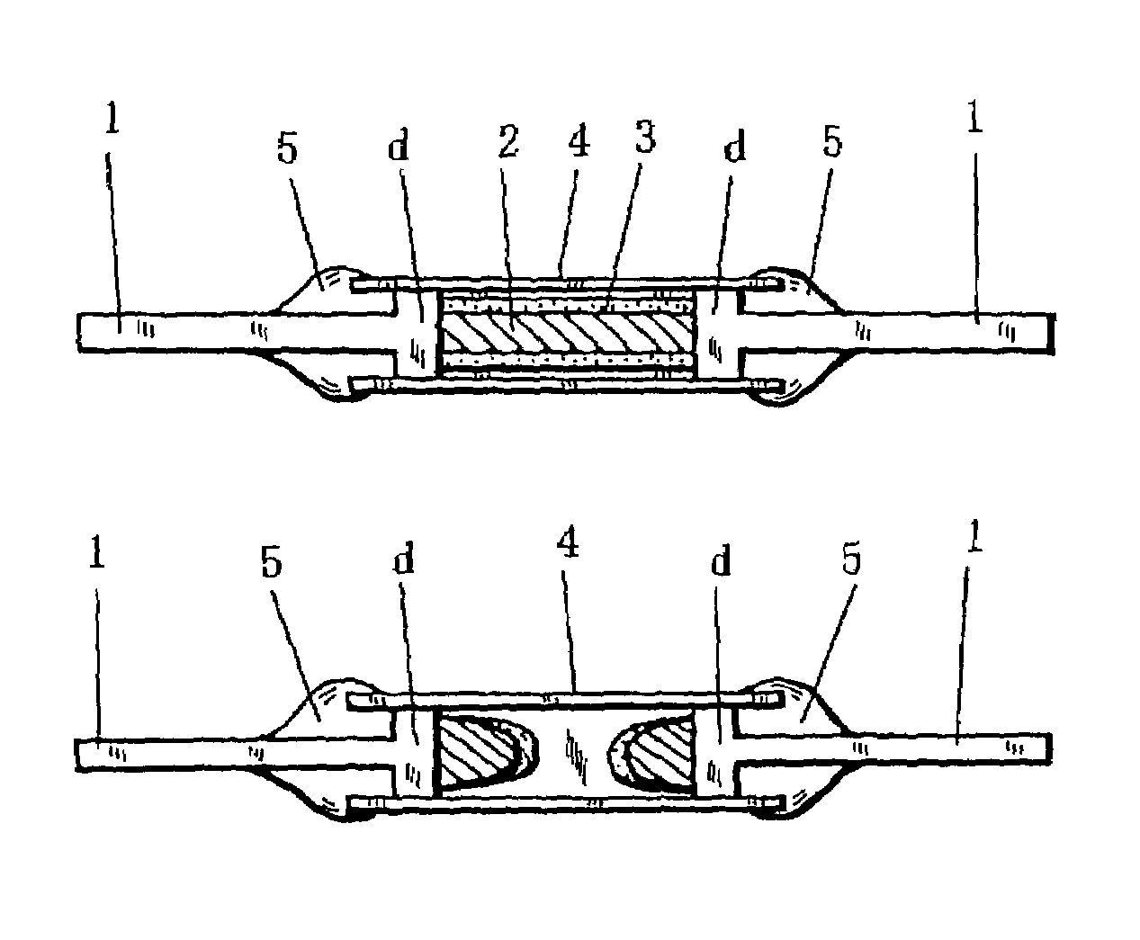
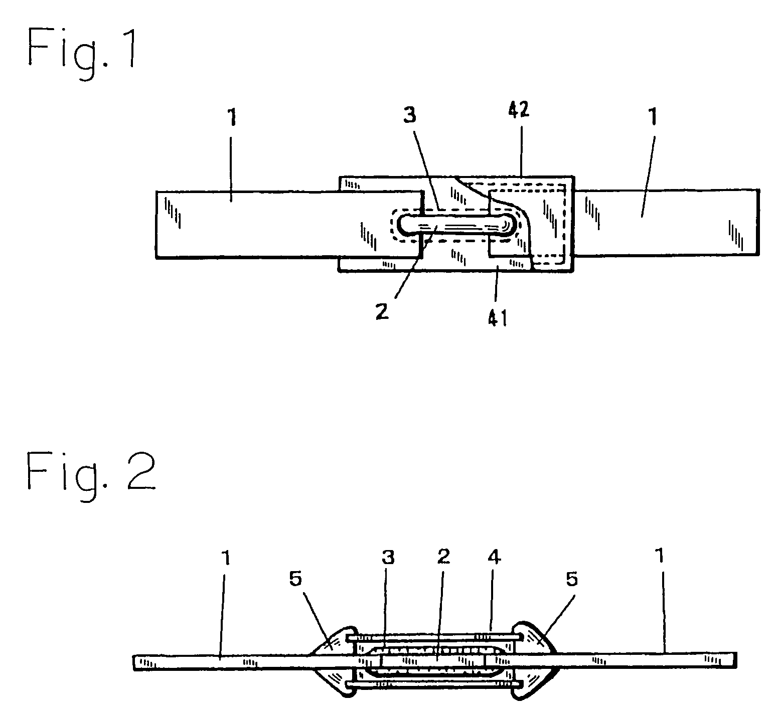
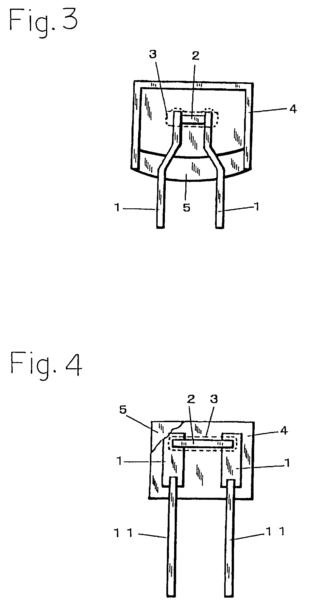
[0076]In the example, alloy type thermal fuses of the cylindrical case type having a fuse element of a composition of 48% Sn, 2% In, and the balance Bi were used.

[0077]Although the thermal fuses were operated under the above-mentioned overload application, the fuses were able to be operated without causing a breakage. The insulation stability after an operation was as follows. The insulation between lead conductors withstood 2×the rated voltage (500 V) for 1 min. or longer, that between the lead conductors and the outer face of the cylindrical case withstood 2×the rated voltage+1,000 V (1,500 V) for 1 min. or longer, the insulation resistance between the lead conductors when a DC voltage of 2×the rated voltage (500 V) was applied was 0.2 MΩ or higher, and that between the lead conductors and the outer face of the cylindrical case was 2 MΩ or higher. As a result, the insulation stability was ◯.

[0078]The fuse element temperature at an operation of the thermal fuse is 135° C., and the ...

examples 2 to 5

[0082]The examples were conducted in the same manner as Example 1 except that the amount of Sn in Example 1 was changed as listed in Table 1 and, in accordance with the change, the amount of Bi was changed.

[0083]In all the examples, in the same manner as Example 1, even when the thermal fuses were operated under the abovementioned overload application, no breakage occurred, and the insulation stability after an overload operation was ◯.

[0084]In all the examples, the element temperature at an operation is lower than the liquidus temperature (by 11 to 13° C.), and it is apparent that the fuse element is broken in the solid-liquid coexisting region. The reason why the insulation stability after an operation is ◯ without causing a breakage during the operation under the overload application is estimated as follows. In the same manner as described above, the division of the fuse element is performed in the wide solid-liquid coexisting region. Therefore, the occurrence of an arc immediate...

examples 6 to 9

[0088]The examples were conducted in the same manner as Example 1 except that the composition of the fuse element in Example 1 was changed as listed in Table 2.

[0089]In all the examples, in the same manner as Example 1, even when the thermal fuses were operated under the overload application, no breakage occurred, and the insulation stability after an overload operation was ◯.

[0090]In all the examples, the element temperature at an operation is lower than the liquidus temperature (by 10 to 12° C.), and it is apparent that the fuse element is broken in the solid-liquid coexisting region. The reason why the insulation stability after an operation is ◯ is identical with that described above.

[0091]In all the examples, the specific resistance of the fuse element is low, and, even under a high load current, self-heating can be sufficiently suppressed so that the thermal fuse can operate at a predetermined temperature.

[0092]Also the drawability of the fuse element in all the examples is ◯....


PUM

PropertyMeasurementUnit
liquidus temperatureaaaaaaaaaa
operating temperatureaaaaaaaaaa

Abstract

An alloy type thermal fuse is provided in which a ternary Sn—In—Bi alloy is used, the operating temperature belongs to the range of 130 to 170° C., the overload characteristic and the dielectric breakdown characteristic are excellent, the insulation stability after an operation can be sufficiently ensured, and thinning of a fuse element can be easily realized. A fuse element having an alloy composition in which Sn is larger than 43% and 70% or smaller, In is 0.5% or higher and 10% or lower, and a balance is Bi is used.

Description

BACKGROUND OF THE INVENTION[0001]1. Field of the Invention[0002]The present invention relates to an alloy type thermal fuse of an operating temperature of about 130 to 170° C., and a wire member for such a thermal fuse element.[0003]2. Description of the Prior Art[0004]An alloy type thermal fuse is widely used as a thermo-protector for an electrical appliance or a circuit element, for example, a semiconductor device, a capacitor, or a resistor.[0005]Such an alloy type thermal fuse has a configuration in which an alloy of a predetermined melting point is used as a fuse element, the fuse element is bonded between a pair of lead conductors, a flux is applied to the fuse element, and the flux-applied fuse element is sealed by an insulator.[0006]The alloy type thermal fuse has the following operation mechanism.[0007]The alloy type thermal fuse is disposed so as to thermally contact an electrical appliance or a circuit element which is to be protected. When the electrical appliance or the...

Claims


Application Information

Patent Timeline
Patent Type & Authority Patents(United States)
IPC IPC(8): H01H85/06H01H85/11C22C12/00B23K35/26C22C13/02C22C30/04H01H37/76H01H69/02
CPCC22C12/00C22C30/04H01H37/761C22C13/02B23K35/262H01H2037/768
Inventor TANAKA, YOSHIAKISARUWATARI, TOSHIAKI
Owner UCHIHASHI ESTEC
Why Eureka
Try Eureka