
Hybrid frequency-time domain equalizer

Inactive Publication Date: 2006-05-09
KONINKLIJKE PHILIPS ELECTRONICS NV
View PDF17 Cites 15 Cited by
  • Summary
  • Abstract
  • Description
  • Claims
  • Application Information

AI Technical Summary

Benefits of technology

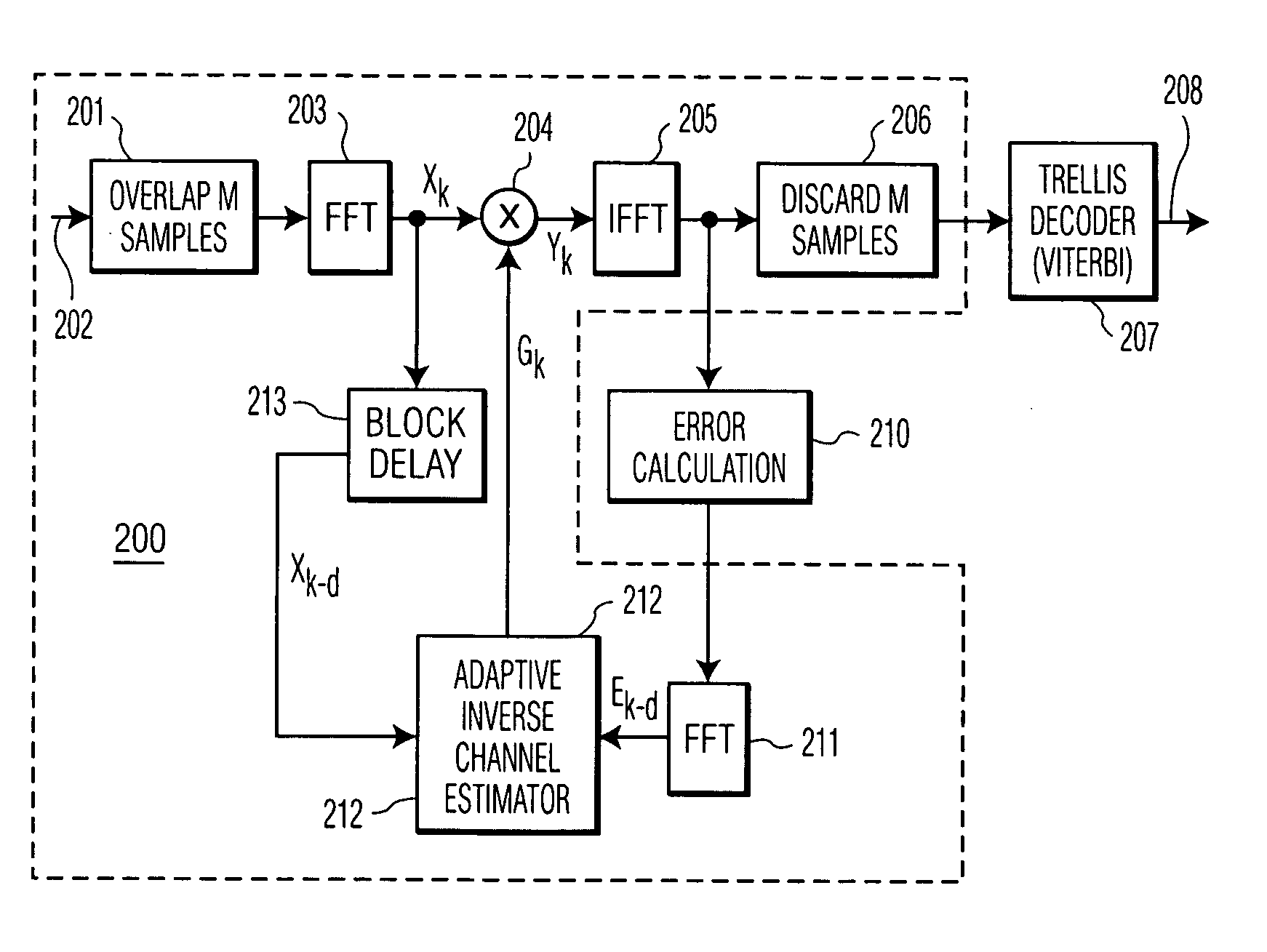
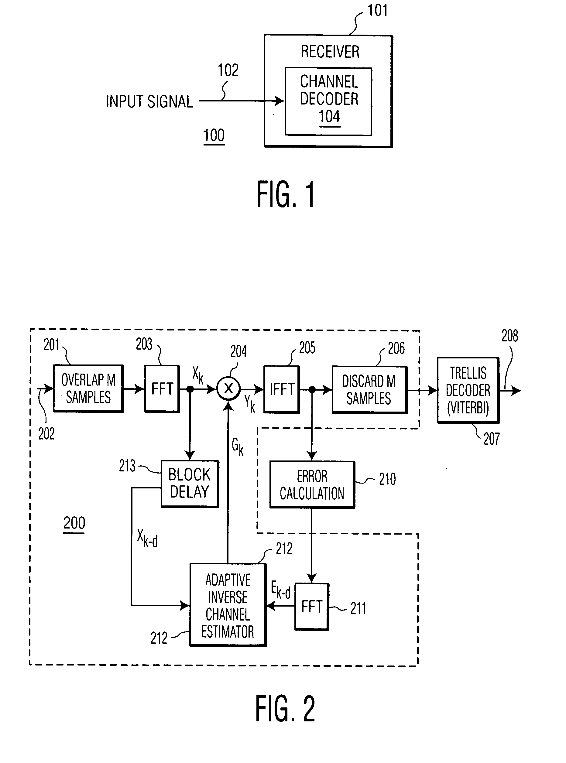
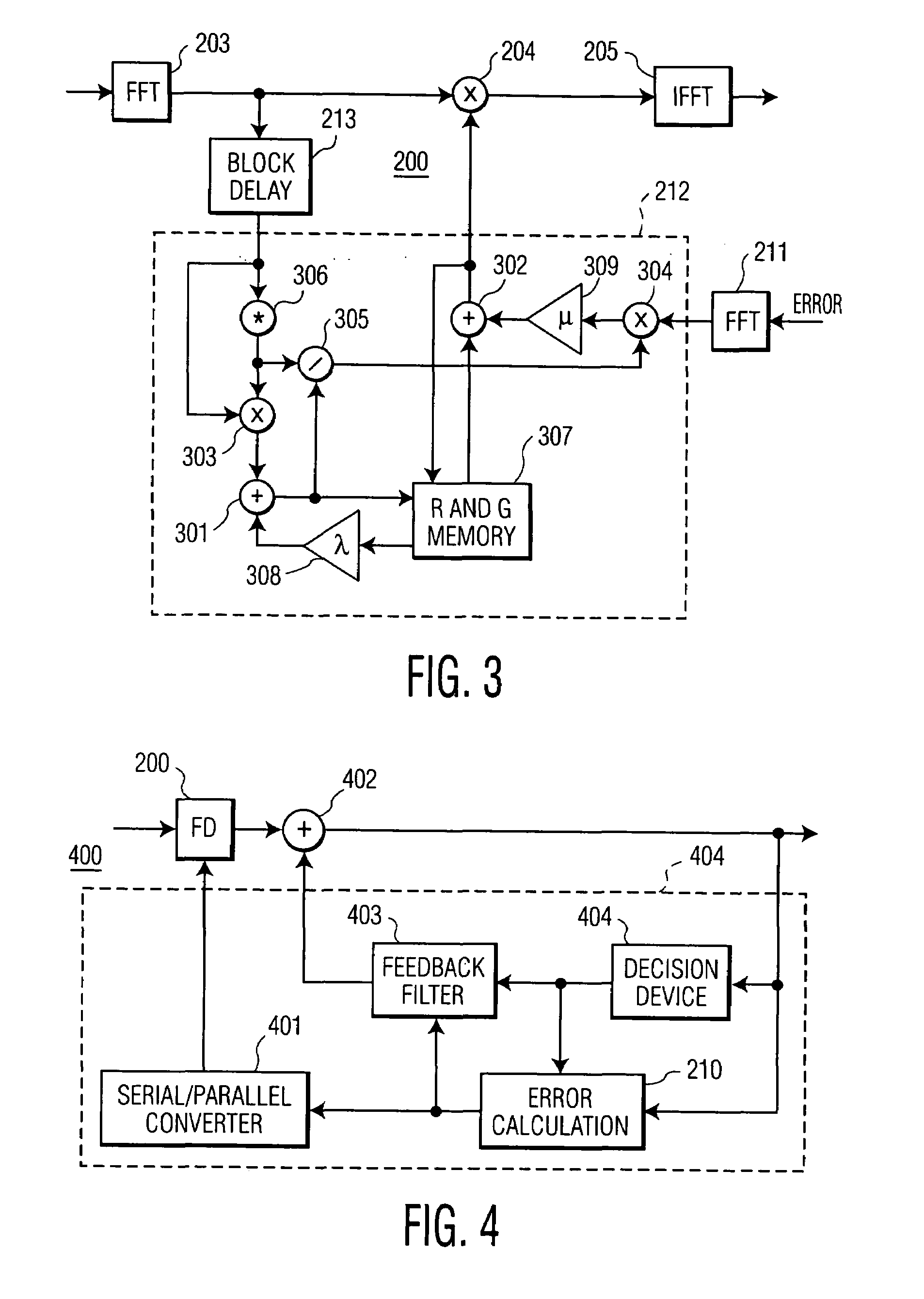
[0008]To address the above-discussed deficiencies of the prior art, it is a primary object of the present invention to provide, for use in a channel decoder, a hybrid frequency-time domain equalizer for effectively combining a frequency domain equalizer with a time domain equalizer to achieve superior static and dynamic multi-path performance compared to conventional decision feedback equalizers. A frequency domain equalizer structure is included within the forward path of a time domain, decision feedback equalizer, with both the frequency domain and time domain portions employing a common error vector. Updates to the taps (frequency bins) may be adapted individually, or fully within the frequency domain without altering the feedback filter. Improved performance, including performance for noisy channels with deep notches, is achieved, and the frequency domain equalizer portion is relieved from equalizing minimum phase zeros of the channel.

Problems solved by technology

Rather than a frequency domain implementation of a time domain finite impulse response (FIR) filter, which is computationally intensive, the frequency domain equalizer disclosed employs a least square cost function which is memory intensive in adaptive inverse channel estimation.
Even though performance of the frequency domain equalizer is at least as good as if not better than the performance of a typical standard time domain decision feedback equalizer (DFE) under the circumstances described, use of the frequency domain equalizer alone may not be adequate to solve the equalization problem of vestigial sideband (VSB) modulation with eight discrete amplitude levels (8-VSB).

Method used


Image

  • Hybrid frequency-time domain equalizer
  • Hybrid frequency-time domain equalizer
  • Hybrid frequency-time domain equalizer

Examples


Embodiment Construction

[0017]FIGS. 1 through 4, discussed below, and the various embodiments used to describe the principles of the present invention in this patent document are by way of illustration only and should not be construed in any way to limit the scope of the invention. Those skilled in the art will understand that the principles of the present invention may be implemented in any suitably arranged device.

[0018]FIG. 1 depicts a system in which a hybrid frequency-time domain equalizer is implemented according to one embodiment of the present invention. System 100 includes a receiver 101, which in the exemplary embodiment is a digital television (DTV) receiver including a channel decoder 104 described in further detail below and capable of demodulating digital television broadcast signals 102 according to the vestigial sideband (VSB) standard, where the digital television signals are received at an input 103.

[0019]Those skilled in the art will perceive that FIG. 1 does not explicitly depict all co...


PUM


Abstract

A channel decoder employs a hybrid frequency-time domain equalizer for effectively combining a frequency domain equalizer with a time domain equalizer to achieve superior static and dynamic multi-path performance compared to conventional decision feedback equalizers. A frequency domain equalizer structure is included within the forward path of a time domain, decision feedback equalizer, with both the frequency domain and time domain portions employing a common error vector. Updates to the taps (frequency bins) may be adapted individually, or fully within the frequency domain without altering the feedback filter. Improved performance, including performance for noisy channels with deep notches, is achieved, and the frequency domain equalizer portion is relieved from equalizing minimum phase zeros of the channel.

Description

RELATED APPLICATION[0001]The present application is related to the subject matter of commonly assigned, co-pending application Ser. No. 09 / 840,203, entitled “A FREQUENCY-DOMAIN EQUALIZER FOR TERRESTRIAL DIGITAL TV RECEPTION.” The contents of the above-identified application is incorporated herein by reference.TECHNICAL FIELD OF THE INVENTION[0002]The present invention is directed, in general, to channel equalization in decoding wireless signals and, more specifically, to hybrid frequency-time domain equalization for improved performance.BACKGROUND OF THE INVENTION[0003]The related application identified above discloses a frequency domain equalizer for vestigial sideband (VSB) decoders implemented within a single integrated circuit multi-standard demodulator also including an orthogonal frequency division multiplexing (OFDM) decoder. Rather than a frequency domain implementation of a time domain finite impulse response (FIR) filter, which is computationally intensive, the frequency d...

Claims


Application Information

Patent Timeline
IPC IPC(8): H03H7/30H03H7/40H03K5/159H04J11/00H04B7/005H04L25/03H04L27/26
CPCH04L25/03006H04L27/2647H04L2025/03617H04L2025/03503H04L2025/03522H04L2025/03382H04N7/015
Inventor BIRRU, DAGNACHEW
Owner KONINKLIJKE PHILIPS ELECTRONICS NV
Learn More