
Manipulator

a manipulator and manipulator technology, applied in the field of manipulators, can solve the problems of not being able to perform the foregoing operative method properly, the operator b>160/b> cannot observe the diseased part directly, and it is difficult for operators to achieve the proficiency of the operative method using the endoscope. achieve the effect of smooth movement, high reliability and satisfactory operability

Inactive Publication Date: 2006-05-09
KARL STORZ GMBH & CO KG
View PDF11 Cites 41 Cited by
  • Summary
  • Abstract
  • Description
  • Claims
  • Application Information

AI Technical Summary

Benefits of technology

The present invention provides a manipulator with simple construction and high reliability and excellent in operability. The manipulator includes an operation command unit, a connecting unit, a working unit, and a control unit. The support unit includes two joints capable of turning about two axes perpendicular to the center axis of the connecting unit. The end effector has two working joints mounted on the second joint, which can rotate in opposite directions to drive the end effector for gripping and releasing actions. The manipulator is connected mechanically, which ensures satisfactory operability and high reliability. The operation command unit can smoothly move in a direction desired by the operator, and the end effector is able to exert a sufficient high gripping force in particular directions.

Problems solved by technology

However, it is a problem in some cases that the operator 160 is unable to observe a diseased part directly.
Accordingly, only skilled operators are able to perform the foregoing operative method properly.
It takes a very long time for operators to attain proficiency in the operative method using the endoscope.
The master / slave manipulator is provided with controllers for controlling slave arms for operations in six degrees of freedom of motion and is a complicated system including many electric control systems, many parts and many wiring lines.
Because of its complexity, the reliability of operations of the master / slave manipulator is not on a satisfactorily high level.
The master / slave manipulator is a large-scale system, expensive and needs a high maintenance cost.
The operator operates the master / slave manipulator at a position remote from the patient and hence the operator is unable to give medical treatment quickly to the patient in an emergency.
Since required operations and the degree of freedom of motion are not properly coordinated in the known medical manipulator shown in FIG. 26, the operation command unit 20 is unable to operate smoothly for operations in directions intended by the operator.
Thus, the operability of the known medical manipulator is unsatisfactory.
Moreover the gripping force of the end effector 14 is insufficient.

Method used


Image

  • Manipulator
  • Manipulator
  • Manipulator

Examples


first embodiment

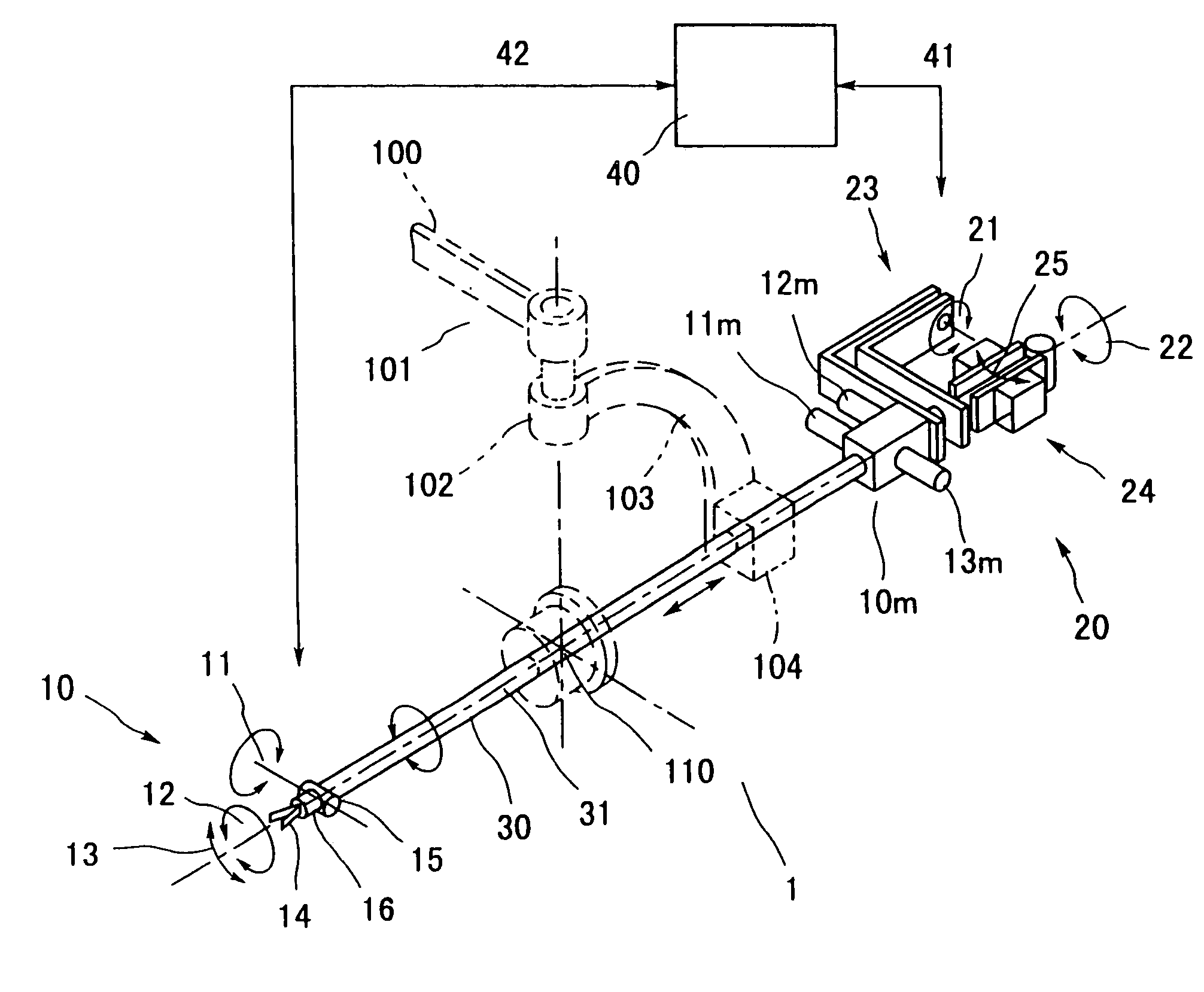
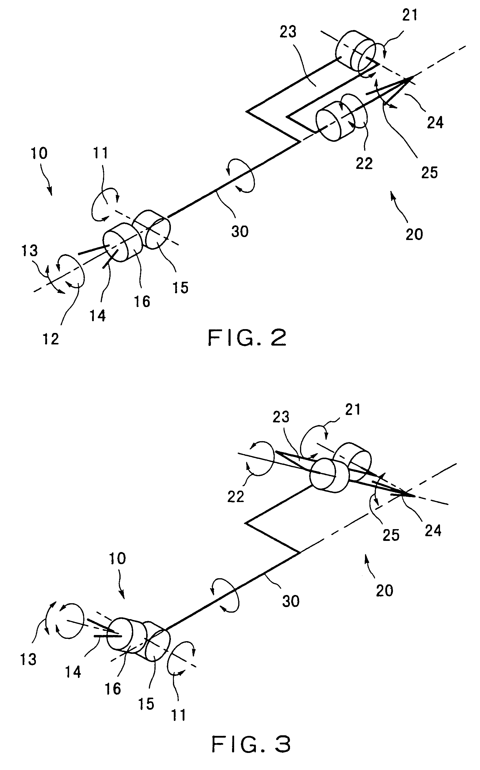
[0049]FIG. 1 is a schematic perspective view of a medical manipulator 1 in a first embodiment according to the present invention, and FIGS. 2 and 3 are skeleton drawings of the medical manipulator 1 shown in FIG. 1 of assistance in explaining the degree of freedom of motion and operations of the medical manipulator 1.

[0050]Referring to FIGS. 1 and 2, the medical manipulator 1 has a working unit 10, an operation command unit 20, and a connecting unit 30 having opposite ends connected to the working unit 10 and the operation command unit 20.

[0051]The working unit 10 has a support unit and an end effector. The support unit includes a first joint 11 having a first rotation axis perpendicular to the center axis 31 of the connecting unit 30 and a second joint 12 having a second rotation axis perpendicular to the first rotation axis of the first joint 11. A gripper 14 included in the end effector and capable of performing gripping / releasing actions 13 has a center axis substantially parall...

second embodiment

[0084]In the first and the second embodiment, the first joint 11 or the third joint 21 is a pitching shaft. However, the first joint 11 or the third joint 21 does not need necessarily to be a pitching shaft and may be a yawing shaft as shown in FIG. 29.

[0085]As apparent from the foregoing description, according to the present invention, since the support unit is able to change the attitude of the end effector in two or more degrees of freedom of motion, the operation command unit and the working unit are connected mechanically by the connecting unit, and the operator's actions, such as actions for manipulating a curved suture needle for suturing, and the actions of the manipulator are identical, the operation command unit can be smoothly moved in a direction desired by the operator. Thus, the manipulator is excellent in operability. Since operating force exerted by the operator is assisted by power when the end effector is set in a singular attitude or an attitude similar to the par...


PUM


Abstract

A manipulator comprises an operation command unit provided with an attitude adjusting unit and an end effector control unit, a connecting unit having one end connected to the operation command unit, a working unit connected to the other end of the connecting unit and provided with an end effector and a support unit supporting the end effector for motions, and a control unit that transmits an operation command provided by the attitude adjusting unit to the support unit to adjust the attitude of the end effector and transmits an operation command provided by the end effector control unit to the end effector to operate the end effector. The support unit includes a first joint capable of turning about a first axis perpendicular to the center axis of the connecting unit, and a second joint capable of turning about a second axis perpendicular to the first axis. The end effector can be turned for rolling about an axis substantially parallel to the second axis of the second joint. The attitude adjusting unit has a third joint having a third axis perpendicular to the center line of the connecting unit. The end effector control unit is formed such that the fingers of an operator gripping operating members included in the end effector control unit extend substantially in parallel to the fourth axis.

Description

CROSS REFERENCE TO RELATED APPLICATION[0001]This application is a division of and claims the benefit of priority under 35 USC §120 to U.S. application Ser. No. 09 / 964,459, filed Sep. 28, 2001, and is based upon and claims the benefit of priority under 35 USC §119 to Japanese Patent Application No. 2000-298365, filed Sep. 29, 2000, the entire contents which hare incorporated herein by reference.BACKGROUND OF THE INVENTION[0002]1. Field of the Invention[0003]The present invention relates to a manipulator and, more particularly, to a medical manipulator of a simple mechanism excellent in operability.[0004]2. Description of the Related Art[0005]Referring to FIG. 25, when practicing laparoscopic surgical operation, such as cholecystectomy, some small holes 151, 152 and 153 are formed in the abdomen of a patient 150 and tubes 154 are inserted in the holes 151, 152 and 153. An endoscope 161 and forcepts 171 and 172 are inserted through the tubes 154 in the abdomen. An operator 160, i.e., a...

Claims


Application Information

Patent Timeline
Patent Type & Authority Patents(United States)
IPC IPC(8): G06F19/00B25J3/00A61B17/28A61B19/00B25J3/04B25J7/00B25J13/02B25J17/02
CPCA61B19/22B25J3/04A61B2019/2242A61B2017/2943A61B2019/2269A61B34/70A61B34/71A61B34/74
Inventor JINNO, MAKOTO
Owner KARL STORZ GMBH & CO KG
Learn More