

Detergent injection systems and methods for carbon dioxide microelectronic substrate processing systems
- Summary
- Abstract
- Description
- Claims
- Application Information
AI Technical Summary
Benefits of technology
Problems solved by technology
Method used
Image

Examples
example 1
[0102]A microelectronic substrate is fabricated by forming a low dielectric constant (low k) material on a microelectronic substrate, such as a silicon semiconductor substrate. The low k material may comprise conventional silicon dioxide and / or silicon nitride dielectrics. In other embodiments, a low k dielectric that is suitable for integrated circuit copper metallization may be used. These low k dielectric materials may comprise silicon dioxide doped with carbon, to provide a dielectric constant of between about 2.9 and about 2.6. Organic low dielectric materials and porous low dielectric materials, such as porous SiLk™ marketed by Dow Chemical, also may be provided with dielectric values approaching 2.0. The use of densified CO2 for cleaning porous dielectrics may be desirable, because it may be difficult to clean these porous low k dielectrics using conventional cleaning techniques.
[0103]A cleaning formulation used to remove low k dielectric etch residues and / or photoresist resi...
example 2
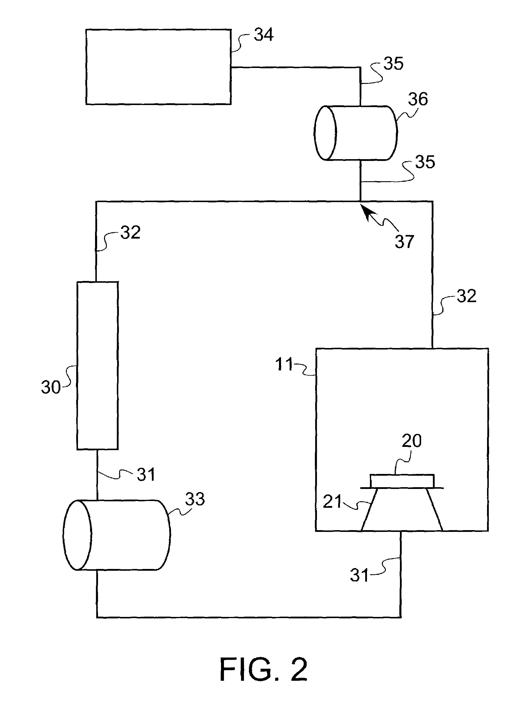
[0105]A cleaning formulation used to remove etch residues from a low k dielectric etched microelectronic substrate is injected into a high pressure densified carbon dioxide based cleaning apparatus that was described, for example, in connection with FIG. 2. The apparatus can include a microelectronic substrate processing chamber 11, a filter 30, a pump 33 for adding carbon dioxide to the chamber and for circulating fluid through the filter and back into the chamber, a cleaning formulation reservoir 34 and associated valves, lines monitors and controls, and a carbon dioxide supply. Initially, carbon dioxide fluid is pumped into the microelectronic substrate processing chamber 11 and associated processing components including the filter 30, and a cleaning formulation supply line 32 and a cleaning formulation drain line 31. Valves are actuated and a pump is activated to circulate fluid between the filter and the cleaning chamber using a carbon dioxide cleaning formulation supply line a...
PUM
 Abstract
Description
Claims
Application Information