Electronic apparatus

a technology of electronic equipment and fins, applied in the field of electronic equipment, can solve the problems of increasing labor and manufacturing costs necessary for that processing, limiting the height and pitch of the fins, and unable to maintain the cooling performance or capacity of the fins to be favorable,

Active Publication Date: 2006-05-16
MAXELL HLDG LTD
View PDF17 Cites 37 Cited by
  • Summary
  • Abstract
  • Description
  • Claims
  • Application Information

AI Technical Summary

Benefits of technology

[0019]Accordingly, an object according to the present invention is to provide an electronic apparatus having a liquid cooling jacket and a liquid cooling system, for use in cooling thereof, with aiming a promotion or enhancement of heat transfer as well as thermal conductivity of a flow passage itself.

Problems solved by technology

For forming the cooling fin, in general, the cutting process is used in many cases; therefore it rises up labor and manufacturing costs necessary for that processing thereof.
On the other hand, with a method for processing with relatively low costs, such as extruding process, for example, but there is a limit in the height and the pitch of the fins, which can be processed; therefore, it is difficult to maintain the cooling performance or capacity thereof to be favorable.
Also, with the structure of providing the injection nozzle, it increases the thickness of the liquid cooling jacket; therefore it is difficult to apply it, in particular, into a narrow space.
However, with the patent document 5, since a brazing material is put therebetween, which has remarkably low heat conductivity, then heat transmission in the direction perpendicular to a base surface is obstructed at this portion, and therefore it is impossible to obtain such the inner thermal resistance that can be obtained when it is formed into a one body, which is processed through the cutting process.
In this manner, though the patent document 3 talks about an improvement on the cooling capacity, however it is impossible to promote or enhance the heat conductivity of the heat sink by itself.

Method used


Image

  • Electronic apparatus
  • Electronic apparatus
  • Electronic apparatus

Examples


embodiment 1

[Embodiment 1]

[0038]Explanation will be made on the first embodiment of the present invention, by referring to FIGS. 1–3.

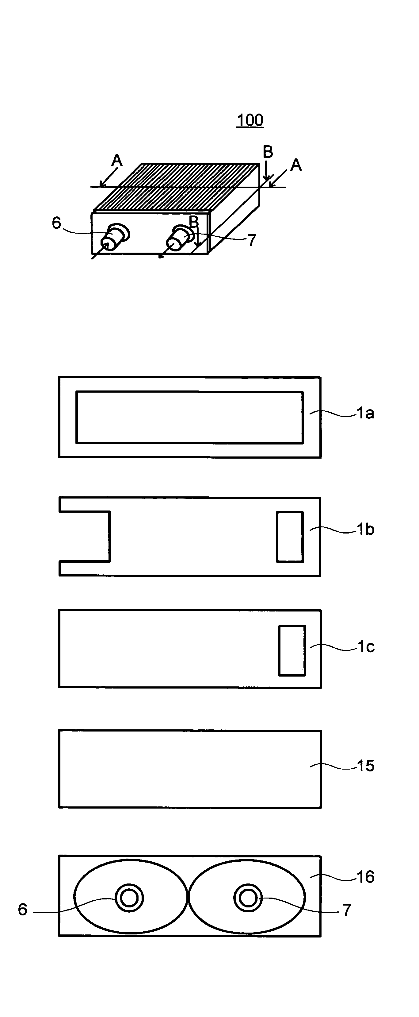
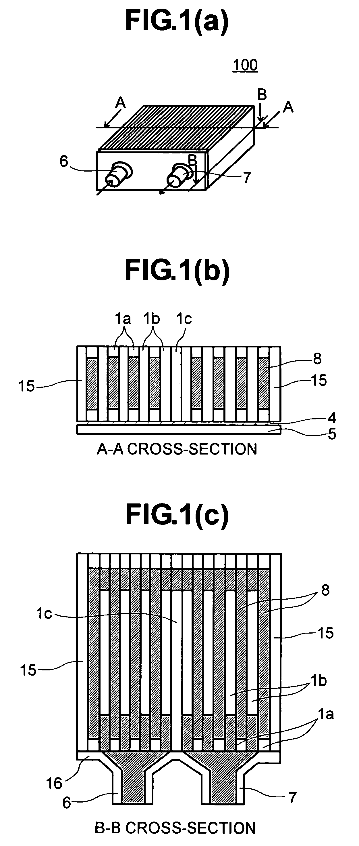
[0039]FIGS. 1(a) to 1(c) are views, including a perspective view of a liquid cooling jacket applying the first embodiment therein and the cross-section views of each part thereof.

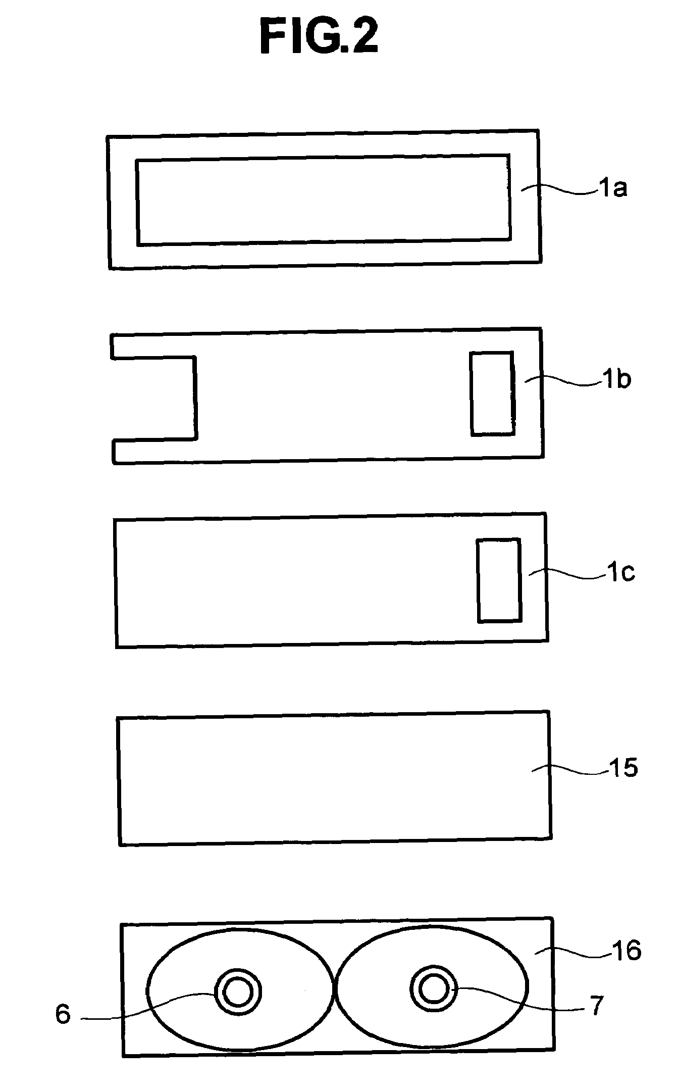
[0040]FIG. 2 is a front view for showing the configuration of a lamination plates, building up the liquid cooling jacket shown in FIGS. 1(a) to 1(c).

[0041]FIG. 3 is a view corresponding to FIG. 2 mentioned above, for explaining a variation of the lamination plates.

[0042]In FIGS. 1(a) to 1(c), the liquid cooling jacket 100, according to the present embodiment, is made up by bonding lamination plates 1a, 1b and 1c made from a thin plate of a metal having superior heat conductivity, such as, copper, for example, which are formed through the punching process (the configurations thereof will be explained in more details, by referring to FIG. 2), being piled up in the direction of thickness the...

embodiment 2

[Embodiment 2]

[0052]FIG. 4(a) is a view of showing the liquid cooling jacket, according to a second embodiment, corresponding to that shown in FIG. 1 mentioned above.

[0053]FIG. 4(b) is a cross-section view of the liquid cooling jacket, in particular, in a case that it is made up with piling up the lamination plates.

[0054]In FIG. 4(a), differing from that of the first embodiment, lamination plates 1e are piled up in the depth direction thereof. Moreover, on this lamination plates 1e, a plural number of holes, being also formed through the punching process, are shifted in one (1) direction (in the example shown in FIG. 4(a), being shifted into the left-hand side), as a whole thereof. And, in the present embodiment, those lamination plates 1e are piled up, being turned upside down with an each piece thereof.

[0055]In other words, since the shifting direction differs from that of the hole formed in each of the lamination plates 1e, the flow passage is meandered or zigzagged around.

[0056]...

embodiment 3

[Embodiment 3]

[0065]FIG. 6(a) is the cross-sectional view of the liquid cooling jacket, according to a third embodiment.

[0066]FIG. 6(b) is the cross-sectional view of the plates being piled up.

[0067]In FIG. 6(a), the lamination plates 1 and 1′, in each of which the holes are formed in zigzagged manner (or, “S”-like shape) through the punching process, are piled up, one by one, each being reversed upside down. Dotted line in the figure depicts the lamination plates 1′ being piled up after being reversed upside down. By means of those zigzag-shaped holes, there is made up the flow passage 8 for the cooling liquid.

[0068]The positions of punching out the holes on the lamination plates 1 are shifted a little bit from the central axis in the horizontal direction, therefore a large number of the overhang portions 14 are defined within the flow passage 8, when piling up the lamination plates 1e and 1e′, alternately reversing upside down. On both ends of the lamination plates 1, 1′ in the ve...


PUM


Abstract

A liquid cooling jacket and a system for use in an electronic apparatus, preferable in the cooling capacity or performance, with less in man-hour and manufacturing costs in need of process thereof, and applicable into a narrow space, wherein a plural number of lamination plates, each being formed through the punching process, are piled up in the width direction thereof, for each piece thereof, and are bonded with each other. A cooling liquid flows in a flow passage defined between the laminating plates, and the laminating plates themselves function as a cooling fin.

Description

BACKGROUND OF THE INVENTION[0001]The present invention relates to an electronic apparatus having a cooling system of a heat-generation element thereof.[0002]Disclosure is made on the structure of a conventional liquid cooling jacket for use in an electronic apparatus, for example, in the following patent documents 1 and 2.[0003]In those patent documents 1 and 2, for the purpose of making an improvement of heat conductive performance or capacity on the liquid side, there is shown the structure, in which a plate-like cooling fin is provided or an injection nozzle is provided, within a cooling liquid passage thereof. For forming the cooling fin, in general, the cutting process is used in many cases; therefore it rises up labor and manufacturing costs necessary for that processing thereof.[0004]On the other hand, with a method for processing with relatively low costs, such as extruding process, for example, but there is a limit in the height and the pitch of the fins, which can be proce...

Claims


Application Information

Patent Timeline
Patent Type & Authority Patents(United States)
IPC IPC(8): F28F7/00F28F3/12B21D53/04F25D17/02F25D9/00G06F1/20H01L23/473H05K7/20
CPCF28F3/12G06F1/20H01L23/473G06F2200/201H01L2924/0002H01L2924/3011H01L2924/00E02D29/0241E02D29/025E02D29/0266E02D2600/20E02D2600/40
Inventor MATSUSHIMA, HITOSHIMATSUSHITA, SHINJIASANO, ICHIROUTAKEUCHI, TSUNENORISUZUKI, OSAMU
Owner MAXELL HLDG LTD
Why Eureka
Try Eureka