Ink jet printing apparatus and ink jet printing method with an air current generating means to remove ink mists generated in the apparatus

a technology of air current generation and ink jet printing, which is applied in the direction of printing, other printing apparatus, etc., can solve the problems of ejecting ink mist from the print head, hindering the formation of appropriate print images, and affecting the effect of printing quality, so as to achieve efficient driving of current generating means, reduce the amount of air current generated, and remove the effect of dropping

Inactive Publication Date: 2006-05-16
CANON KK
View PDF11 Cites 12 Cited by
  • Summary
  • Abstract
  • Description
  • Claims
  • Application Information

AI Technical Summary

Benefits of technology

[0018]In the present invention, if a large amount of ink is provided per unit time owing to, for example, a high print duty or if spacing between the print medium and the print head are large, ink mists that may be generated in the apparatus are reliably removed by increasing the time for which the current generating means is driven and/or the amount of air currents generated per unit time. On the other hand, if no printing...

Problems solved by technology

However, if a printing operation is performed using the ink jet method, then in addition to ink droplets contributing to image printing, fine ink droplets (ink mists) not contributing to image printing are ejected from the print head.
They may hinder the formation of appropriate print images.
However, when the ink mists adhering to and accumulating on the platen, a print paper conveying roller, or the like become more viscous, the print medium cannot be smoothly conveyed.
Moreover, if ink mists adhere to the vicinity of a movable part such as a sliding shaft or bearing on a carriage, the movable part may undergo severer friction to disable normal operations.
Furthermore, if ink mists adhere to an encoder located near the carriage or an optical part such as a reflection type photo sensor used to detect the position of a print medium or the carriage, it becomes impossib...

Method used


Image

  • Ink jet printing apparatus and ink jet printing method with an air current generating means to remove ink mists generated in the apparatus
  • Ink jet printing apparatus and ink jet printing method with an air current generating means to remove ink mists generated in the apparatus
  • Ink jet printing apparatus and ink jet printing method with an air current generating means to remove ink mists generated in the apparatus

Examples


first embodiment

(First Embodiment)

[0025]First, a first embodiment of the present invention will be described with reference to FIGS. 1 to 4.

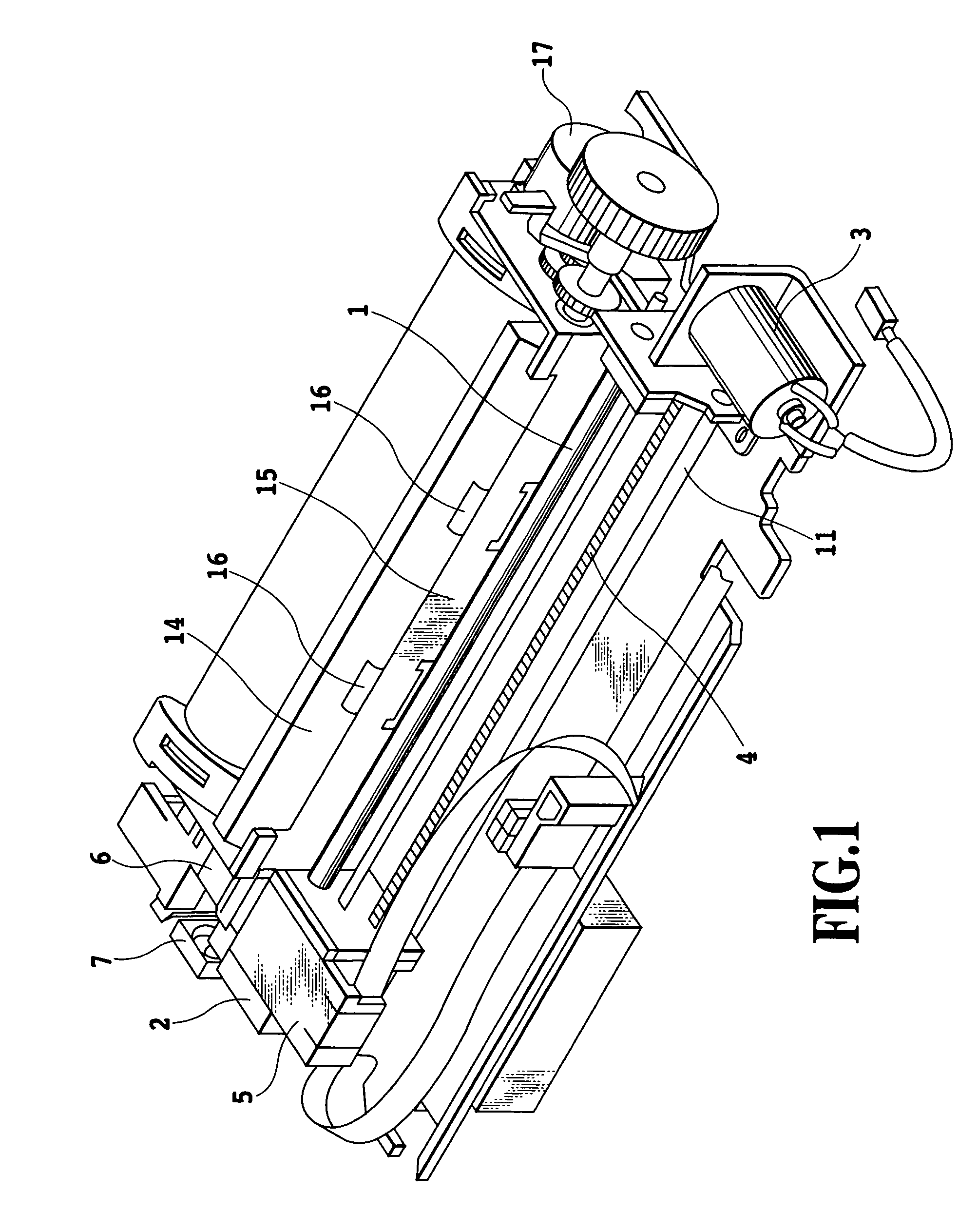
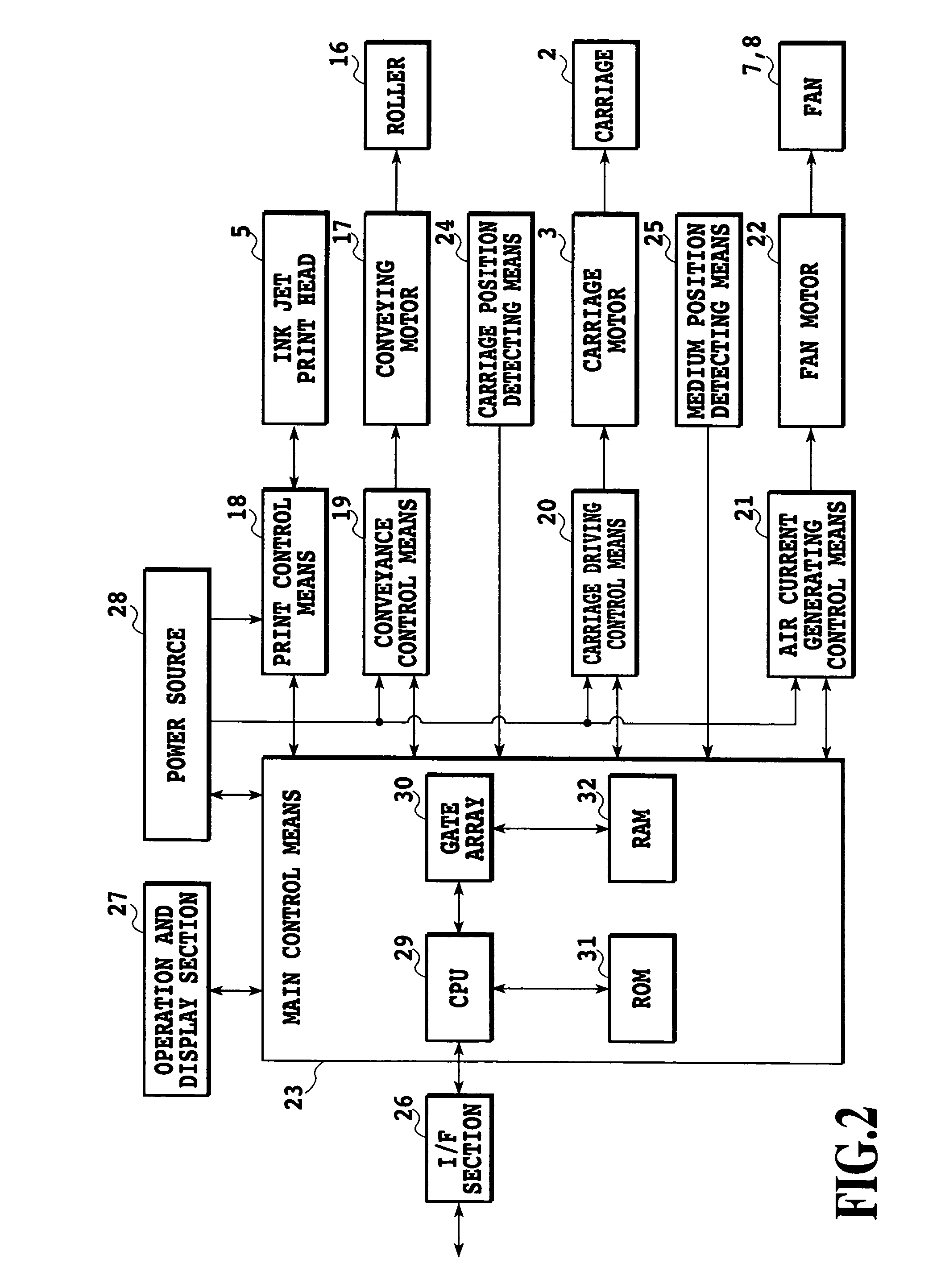
[0026]FIG. 1 is a perspective view schematically showing the appearance of an ink jet type printing apparatus as a first embodiment of the present invention. As shown in this figure, a carriage 2 is slidably attached to shafts 1 and 11 fixed to a frame of the ink jet printing apparatus. The carriage 2 is driven by a carriage motor 3 and a carriage belt 4 that are carriage driving means, to reciprocate along the shafts 1 and 11. An ink jet head 5 as printing means according to the present embodiment is mounted on the carriage 2. A large number of nozzles are formed in the ink jet head 5 and contain respective energy generating elements such as heating elements which generate ink ejection energy. When any of the energy generating elements is driven in response to a print control signal, described later, the print head ejects ink from the nozzle corresponding to t...

second embodiment

(Second Embodiment)

[0050]Now, a second embodiment of the present invention will be described with reference to the drawings. The second embodiment is configured as shown in FIGS. 1 and 2 as in the case with the first embodiment.

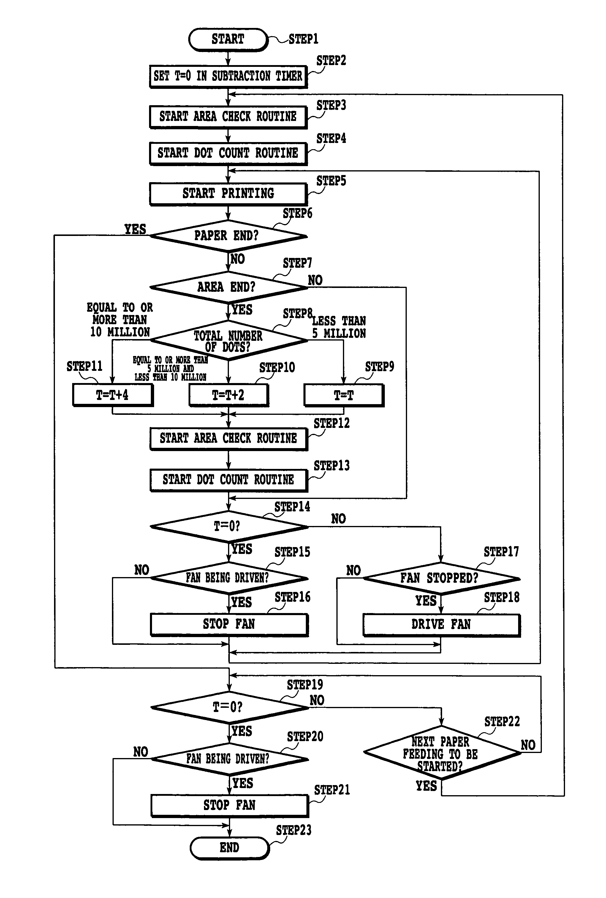
[0051]With reference to the flowchart in FIG. 4, description will be given of a control operation according to the second embodiment.

[0052]First, when the printing apparatus is powered on at STEP1, a paper feeding operation is performed at STEP2. Subsequently, at STEP3, a voltage V1 is provided to the fan motor 22 as a driving voltage V to rotate the fan 7. Then, at STEP4, an area check is started to manage the amount of print medium fed by rotation of the conveying motor 17. In the second embodiment, area management is carried out every inch to determine whether or not the print position has reached the area end. At STEP5, the dot count routine is started to count the number of dots in each area. The count obtained is used to determine the fan driving time.

[...

third embodiment

(Third Embodiment)

[0059]In the first and second embodiments, the driving conditions for the air current generating means is determined on the basis of information on the number of print dots per unit area (each area). The present invention is not limited to this aspect.

[0060]That is, the amount of ink provided does not depend only on the number of print dots but also on other conditions (for example, an environment temperature or a head temperature). Specifically, the amount of ink provided tends to increase consistently with the environment temperature. In contrast, the amount of ink provided tends to decrease consistently with the environment temperature. That is, even with the same number of print dots, the amount of ink provided is relatively large when the environment temperature is high. In contrast, the amount of ink provided is small when the environment temperature is low. Accordingly, to determine more accurately the amount of ink provided per unit area, it is preferable t...


PUM


Abstract

It is an object of the present invention to provide an ink jet printing apparatus which can appropriately remove ink mists generated in the apparatus and which can avoid wasteful energy consumption. Thus, the present invention provides an ink jet printing apparatus that carries out printing on a print medium using ink, the apparatus including an air current generating portion that generates air currents inside the printing apparatus, a determining section that determines driving conditions for the air current generating portion on the basis of information on the amount of ink to be provided per unit area of a print medium, and a control section that controls the air current generating portion in accordance with the driving conditions determined by the determining section.

Description

[0001]This application claims priority from Japanese Patent Application No. 2002-320431 filed Nov. 1, 2002, which is incorporated hereinto by reference.BACKGROUND OF THE INVENTION[0002]1. Field of the Invention[0003]The present invention relates to an ink jet printing apparatus that carries out printing using ink.[0004]2. Description of the Related Art[0005]Printing apparatuses have functions for a printer, a copier, or a facsimile machine or are used as output equipment for composite electronic equipment or a workstation including a computer or a word processor. These printing apparatuses are configured to print images on printed materials (print media) such as paper or thin plastic sheets on the basis of image information. The printing apparatuses can be classified into an ink jet type, a wire dot type, a thermal type, a laser beam type, and others in terms of a printing method.[0006]A serial type printing apparatus employs a serial scan method of moving the apparatus in a main sc...

Claims


Application Information

Patent Timeline
IPC IPC(8): B41J2/165B41J2/01B41J29/17B41J29/38
CPCB41J2/165B41J29/38B41J29/17
Inventor SHIMOYAMA, NOBURO
Owner CANON KK
Why Eureka
Try Eureka