Apparatus and method for improving the control of a concrete screed head assembly

a technology of concrete screeding and control apparatus, which is applied in the direction of construction, construction, and building material handling, can solve the problems of increasing the difficulty of maneuvering forklift machines along the aisle, and increasing the difficulty of navigating the aisle, so as to improve the control of the concrete screeding assembly, improve the surface quality of the concrete floor, and avoid the effect of minimizing the creation of vibrating member depressions

Active Publication Date: 2006-05-16
SOMERO ENTERPRISES INC
View PDF31 Cites 62 Cited by
  • Summary
  • Abstract
  • Description
  • Claims
  • Application Information

AI Technical Summary

Benefits of technology

[0019]More specifically, the present invention provides an apparatus and method that improves the control of a concrete screeding assembly during the process of “landing” at the beginning of each screeding pass. Through the use of sensors, mechanical actuators, and an automated controller, and including methods of positioning the vibrating member relative to a screed head assembly in overlap areas, the automated control system of the present invention provides a significant improvement in the surface quality of a concrete floor. The present invention provides a means of sensing the firmness characteristics of the concrete and includes a control system for automatically minimizing the creation of vibrator landing depressions made in the overlap areas of previously screeded concrete. The apparatus and method of the present invention may be generally referred to as a “soft landing” control system for concrete screeding machines.
[0020]The present invention provides an automated apparatus and means of preventing the vibrating member from substantially engaging the already set-up concrete a second time in overlap areas. A solution to help solve this problem is to temporarily and independently raise the vibrator relative to the plow and auger. Raising the vibrator up about one quarter inch (6 mm), for example, from the concrete whenever the vibrator is likely to engage previously screeded concrete prevents a second vibration of the material. This is useful where concrete that is beginning to set-up it is not likely to rebound after a second engagement by the vibrator.
[0021]The present invention provides an apparatus and method to avoid and minimize the creation of vibrating member depressions in a concrete surface where the screed head re-engages previously screeded concrete material. It also provides a control means for automated and controlled descent of the screed head for re-engagement with the concrete. The apparatus and method of the present invention thus improves the finished surface quality of a screeded concrete surface.
[0022]The present invention provides an automatic control system and apparatus for sensing the presence and / or condition of the concrete and providing a signal indicative of such presence and / or condition as an input to a controller. The controller then provides an output signal to automatically achieve a desired adjustment of the concrete screeding head. This includes temporarily tilting or rotating the screed head assembly of a concrete screeding apparatus to raise the vibrating member to reduce or eliminate its engagement with the concrete, or lifting the vibrating member independently with respect to the plow and auger means. Any depressions typically created in the concrete surface by the vibrating member within overlap areas thus become substantially reduced or eliminated.
[0023]The screeding device of the present invention thus may include an electronic control feature which may improve the quality and smoothness of the screeded concrete surface by temporarily tilting the screed head, or auger support beam and vibrator, auger and plow, toward the operator as the screed head assembly is lowered onto the uncured concrete or other material surface. The tilting action allows the vibrating device to not penetrate its normal distance (such as approximately 0.25 inches) into the uncured concrete as it is lowered onto the uncured concrete surface. Such an action may be especially useful in landing locations where the uncured concrete has already begun to set up somewhat and has lost its ability to spring back up to the desired grade after the vibrating member has passed over the partially set up concrete material. The soft landing function is intended to improve floor quality F-numbers.

Problems solved by technology

Large vertical offset errors at the forklift forks result in an increasingly greater difficulty in maneuvering the forklift machines along the aisles and while reaching for materials and goods at the upper most shelves.
Therefore, flatness or levelness errors in the concrete floor become a limiting factor in the practical design of high-density vertical-storage warehouse facilities.
In locations where land or real estate values are high or available space is at a premium, such costs are an important factor.
Super-flat floors are typically expensive for building owners to buy and concrete contractors to produce, since such projects usually require specialized equipment and experienced personnel with a thorough working knowledge of the process.
Because of the relatively higher cost of the super-flat floors, often only specified areas of a building floor will be made to super-flat specifications, such as within anticipated aisleways of a given floor plan.
When changes for the floor plan are necessary however, the spacing and location of the aisle ways cannot be easily adjusted or moved.
This limitation increases renovation costs and possibly reduces the future investment value and long-term usefulness of the facility.
Super-flat concrete floors are much more difficult and expensive to achieve than those conventionally poured.
However, a large number of workers are required to finish the floor.
Production speed of the floor is thus relatively slow with such a conventional process.
Additionally, as even the best skilled worker continues to use his tools of the trade, over the course of a day, the worker will fatigue and tire as the day goes on.
Human endurance has its typical limitations.
This factor can also have an adverse effect on the final F-numbers and quality of the floor.
Therefore, because many flat surfaces are finished by manual labor, the surfaces are likely to have relatively poor or inconsistent quality with regard to overall levelness and flatness.
There exist, however, limitations toward achieving super-flat high quality floors that are a result of the above-described physical aspect.
However, access to the concrete surface can be a limitation.
Workers using these tools may be greatly limited during “wide placement” site conditions or high rates of production.
However, the actual accuracy of the finished concrete floor surface is likely to remain in question.
With super-flat concrete floors, however, the created landing depressions become an even greater limitation toward achieving high-quality floors having high F-number characteristics.
However, such soft landings can be difficult to achieve on a consistent or repeatable basis, and are largely dependent on the level of skill and experience of the screeding machine operator.
The length of time is not easily determined and is subject to many variables such as the prevailing conditions that exist at the site or the mix design of the concrete.
Warm, dry and windy conditions may cause the concrete to quickly dry and harden at the surface, while cool and damp conditions may have the opposite effect.
Also, low slump concrete may be more difficult to work, but often offers higher cure strength by containing less water in the mixing ratio.
If contact between the vibrator and the earlier smoothed concrete is made and sustained, there exists a high likelihood that a landing depression or other irregularity will be created in the previously smoothed and already setting concrete.
Cold joints are usually minimized as much as possible, however the complete elimination of overlap areas is not reasonably practical.

Method used


Image

  • Apparatus and method for improving the control of a concrete screed head assembly
  • Apparatus and method for improving the control of a concrete screed head assembly
  • Apparatus and method for improving the control of a concrete screed head assembly

Examples


Embodiment Construction

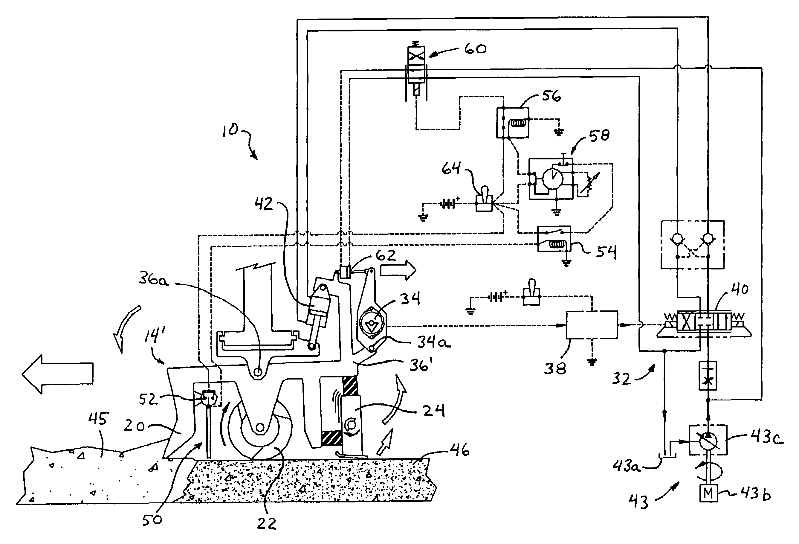
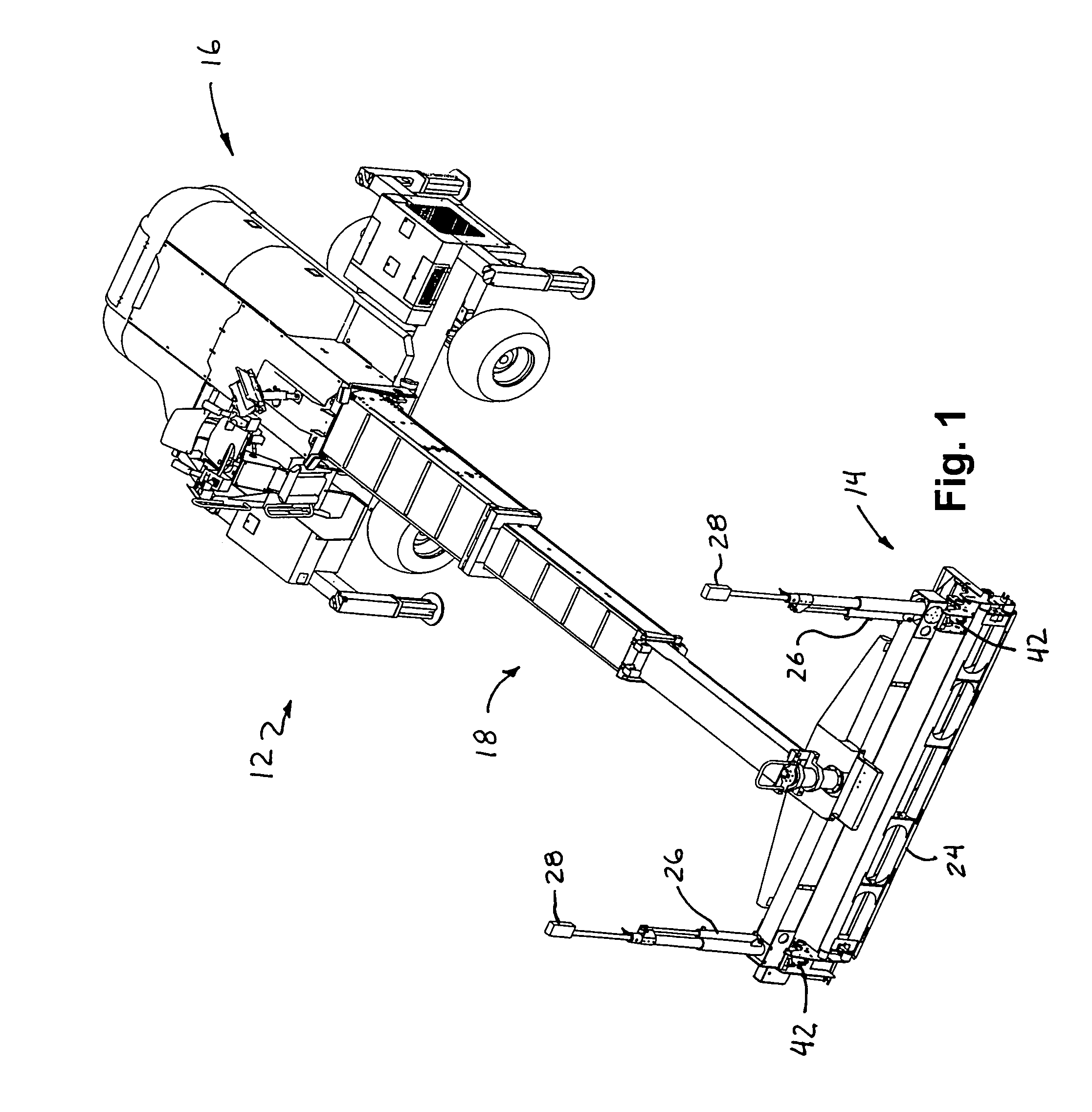
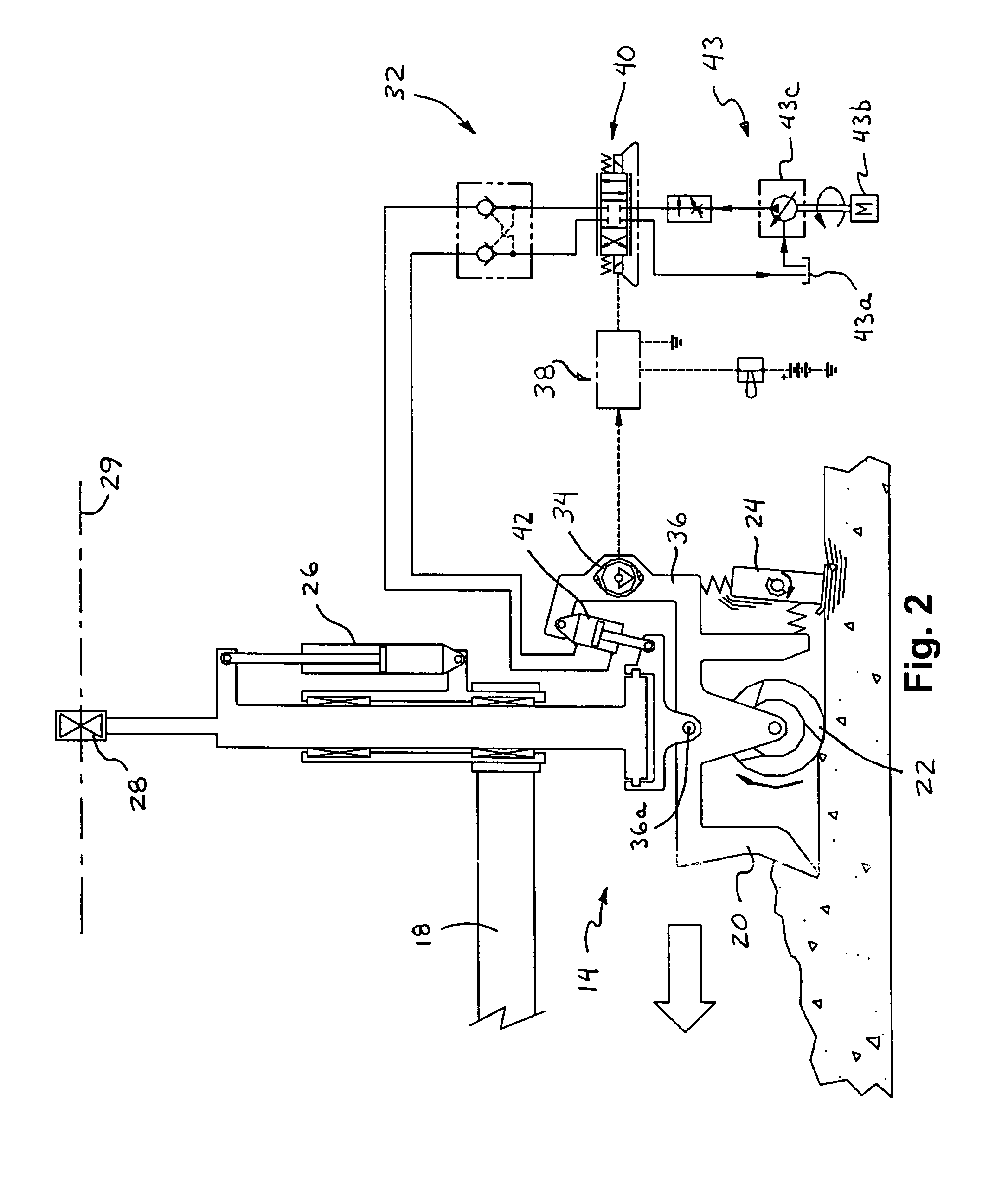
[0062]Referring now specifically to the drawings and the illustrative embodiments depicted therein, an automated soft landing control system 10 for a concrete screeding machine or device 12 is automatically operable to control the landing of the screed head assembly 14 onto a concrete surface (FIGS. 1 and 4A–C). Soft landing control system 10 may be applied to a concrete screeding machine to substantially improve the quality of concrete floors at overlapping or cold-joint areas of the leveled and smoothed concrete. Soft landing control system 10 is operable to delay engagement of the vibrating member of the screed head assembly with the concrete surface until after the vibrating member has moved from the overlap area of already screeded concrete to an area of not yet screeded concrete, in order to reduce or substantially preclude damage or depressions or irregularities in the already screeded concrete, as discussed below.

[0063]Concrete screeding machine 12 may comprise any type of c...


PUM


Abstract

A soft landing control system for a screeding device is operable to automatically lower a vibrating member of a screed head assembly into engagement with a concrete surface at a time and place where the vibrating member is not positioned over an overlap area of already screeded concrete. The vibrating member is automatically lowered onto newly placed concrete at or near the junction or cold-joint between the already screeded concrete and the area of newly placed concrete, so as to avoid depressions in the already placed concrete. Optionally, the soft landing control system may include a timing device and may lower the vibrating member after a period of time following an activating event. Optionally, the control system may detect when the vibrating device is positioned at or near the newly placed concrete and may lower the vibrating member in response to such detection.

Description

CROSS REFERENCE TO RELATED APPLICATION[0001]The present application claims benefit of U.S. provisional application, Ser. No. 60 / 457,260, filed Mar. 25, 2003 by Torvinen for SCREED HEAD ASSEMBLY, which is hereby incorporated herein by reference in its entirety.FIELD OF THE INVENTION[0002]The present invention relates generally to an apparatus and method for controlling a concrete screeding assembly during the leveling and smoothing of freshly poured concrete, as well as somewhat partially cured concrete, that has been placed over a surface.BACKGROUND OF THE INVENTION[0003]There is a continuous and growing need within industry for flat and level close-tolerance concrete floors used in a variety of structures such as office buildings, shopping centers, warehouses, and production and / or manufacturing facilities. Most modern production and manufacturing plants include high-precision machinery and equipment which must be set level on a flat surface. A main benefit from achieving close-tol...

Claims


Application Information

Patent Timeline
Patent Type & Authority Patents(United States)
IPC IPC(8): E01C23/07E01C19/00E01C19/40E04F21/24E04G21/06
CPCE01C19/006E01C19/40E04G21/066E04F21/24E01C19/405E01C2301/20E04F21/247
Inventor QUENZI, PHILIP JKIERANEN, CARL BANDERSON, FRANK ETORVINEN, JEFFREY WPIETILA, MARK A
Owner SOMERO ENTERPRISES INC
Why Eureka
Try Eureka