Process for treating waste oil

a technology for treating waste oil and waste oil, which is applied in the field of purification, can solve the problems of only efficiently disposing of used oil, no equipment available to easily and cost-effectively remediate waste streams on-site, and potential liability of the generator

Inactive Publication Date: 2006-05-16
INDAL MICROWAVE TECH
View PDF13 Cites 6 Cited by
  • Summary
  • Abstract
  • Description
  • Claims
  • Application Information

AI Technical Summary

Benefits of technology

[0030]Preferably, the apparatus further comprises a preheating section connected upstream of the preprocessing switch. Most preferably, the preheating section is a resistance heater or a heat exchanger, or both. Preferably the heating section comprises both resistance heating and microwave heating. Most preferably, the microwave heating section comprises a waveguide and a slurry conduit extending through a portion of the waveguide. Most preferably, the waveguide includes a straight member between a first end and a second end, the first end is a curved member having a 45°“H”-plane bend of miter construction. Preferably, the apparatus further comprises a post processing analyzer section connected to a demulsifier output, and a post-processing switch connected to a post-processing analyzer section output of the post-processing analyzer section.

Problems solved by technology

However, under current United States laws, having used oil picked up does not remove the potential liability from the generator.
Moreover, such used oil can only be efficiently disposed of (e.g., through combustion) if it is treated to remove aqueous contamination.
There is no equipment available that can easily and cost-effectively remediate these waste streams on-site.
This service is costly.
Depending on the characteristics of the oily waste stream and petroleum market conditions, the cost of this service varies.
This process for removing water from used oils is complex, costly, time consuming and produces waste components that require further remediation (rag layer).
It should be noted that even with bench testing and a good result with a particular demulsifer, this does not always lead to a successful result during the production run, which requires the production batch to be processed again.
This batch process is complex (not fool proof), lengthy, and somewhat labor intensive.
It is also costly having rising natural gas costs for heating and demulsifier costs.
However, these methods do not recover a fully marketable product.
They provide only partial separation and typically leave large amounts of regulated waste.
Those methods that do recover some marketable oil are inefficient, making satisfactory results difficult to obtain.
Specifically, conventional heating methods suffer from slow heat transfer between the heating element and thick emulsions, accumulation of heavy layers of solid residue on heat transfer surfaces, and loss of volatiles.
Chemical demulsifiers, such as alum and polyamines, can be used to separate oil / water emulsions, but these chemicals are subject to very strict government regulation concerning their discharge into public water.
In addition, chemical treatment can be a relatively slow process with an inefficient separation of some emulsions.

Method used


Image

  • Process for treating waste oil
  • Process for treating waste oil
  • Process for treating waste oil

Examples


case 1

[0093] Conventional Heating

[0094]100 mL of slop oil having an estimated 11% water by volume was dosed with 3000 ppm of 906 polymeric demulsifier (Midwestern Custom Chemicals). The sample then was place in a 60° C. hot water bath for thirteen hours. The sample was then allowed to cool for eleven hours. A visual measurement showed 2% water released four hours after the start of heating. The sample still had 2% water released (by volume) after allowing it to cool for eleven hours.

case 2

[0095] Microwave Heating-1

[0096]Slop oil having an estimated 11% water by volume (same as above case 1) was dosed with 3000 ppm of 906 demulsifier from Midwestern Custom Chemicals. Note that this case was a semi-continuous processing, while case 1 was a batch processing. The oil was then heated by microwave energy to approximately 49° C. The oil was then placed in a 60° C. hot water bath for thirteen hours. The sample was then allowed to cool for eleven hours. 100 mL samples were drawn off for testing. At four hours after being placed in the hot water bath the sample showed 25% water released by volume. After allowing the oil to cool for eleven hours the sample showed virtually all water released.

case 3

[0097] Microwave Heating-2

[0098]This case is similar to case 2 except the oil was not placed in the hot water bath. After the microwave heating the sample was allowed to cool to ambient temperature. The sample showed no visual sign of separation.

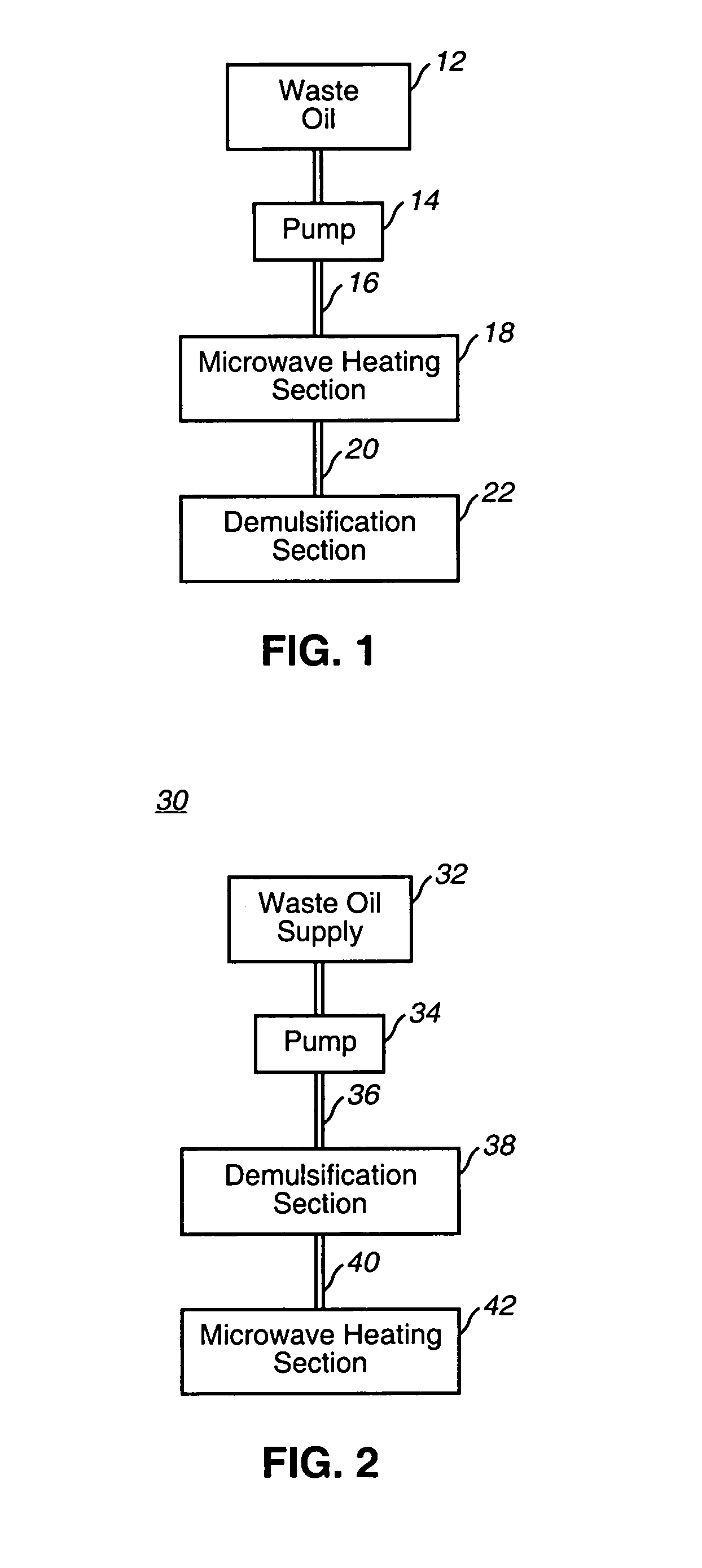
[0099]Heating before Demulsification


PUM

PropertyMeasurementUnit
temperatureaaaaaaaaaa
temperaturesaaaaaaaaaa
temperatureaaaaaaaaaa

Abstract

There is disclosed a burnable used oil fuel product by the process comprising:
    • (a) obtaining a used oil sample having at least 1% (by weight) aqueous substances;
    • (b) heating the used oil sample to a temperature of from about 20° C. to about 60° C.; and
    • (c) extracting a volume of water from the heated used oil by adding super critical CO2.

Description

RELATED APPLICATIONS[0001]The present invention claims priority on provisional patent applications, Ser. No. 60 / 171,915, filed on Dec. 21, 1999, and Ser. No. 60 / 198,630, filed on Apr. 20, 2000.TECHNICAL FIELD OF THE INVENTION[0002]The present invention relates generally to the field of purification and more particularly to a method for purifying waste oil.BACKGROUND OF THE INVENTION[0003]Used lubricating and hydraulic oils are generated, for example, by automotive and commercial shops, large industrial manufacturing facilities, marine facilities and airline and railroad maintenance departments. Used oils are generally considered hazardous wastes and are heavily regulated. Generators of used oils are responsible for cradle to grave management (RICRA) of these waste streams. Generators have generally contracted with used oil recyclers to pick up the waste and remediate it or dispose of it under the laws that regulate the transport, processing and destruction of the various components ...

Claims


Application Information

Patent Timeline
Patent Type & Authority Patents(United States)
IPC IPC(8): B01D3/00B01D17/00C10M175/02C10G32/02C10L1/00C10M175/00
CPCB01D17/005C10G32/02C10L1/00C10M175/005B01D17/0208B01D17/0214B01D17/047
Inventor SCHAEFER, FREDERICK ANTHONY
Owner INDAL MICROWAVE TECH
Why Eureka
Try Eureka