Column simultaneously focusing a partilce beam and an optical beam

a partilce beam and optical beam technology, applied in the field of collimation simultaneously focusing a partilce beam and an optical beam, can solve the problems of difficult intervention in the depth of the circuit, the inability to apply focused ion beams to provide an in-depth image of a solid, and the inability to achieve the effect of reducing the aberration of output electrodes

Inactive Publication Date: 2006-05-16
ORSAY PHYSICS +1
View PDF69 Cites 45 Cited by
  • Summary
  • Abstract
  • Description
  • Claims
  • Application Information

AI Technical Summary

Benefits of technology

[0018]an optical focusing device for simultaneously focusing a light beam, carrying an outlet opening,such column making it possible to associate:

Problems solved by technology

One of the limits of applying focused ion beams is the impossibility of employing them to provide an in-depth image of a solid.
In the case of passivated and planarized integrated circuits, a surface image gives no information on the underlying layers and circuits, which has the disadvantage of making any intervention in the depth of the circuit extremely difficult such as, in particular, the cutting or breaking of buried metal tracks made necessary by design and failure analysis.
The final diameter chosen for the outlet aperture is consequently a trade-off which is not satisfactory either for the optical beam extent or for ion beam focusing.
Secondly, the system disclosed in French patent 2,437,695 necessitates a very small (a few millimetres) working distance and the submitting of the sample to an electrical field.
These two constraints are unacceptable in focused ion beam technology applied to integrated circuits: the danger of destroying the circuits by micro-electrostatic breakdown, impossibility of slanting the sample, difficulty in collecting secondary electrons, and the practical impossibility, through lack of space, of associating the system with a capillary tube for injecting pre-cursor gas which is an essential accessory in focused ion beam technology.

Method used


Image

  • Column simultaneously focusing a partilce beam and an optical beam
  • Column simultaneously focusing a partilce beam and an optical beam
  • Column simultaneously focusing a partilce beam and an optical beam

Examples


Embodiment Construction

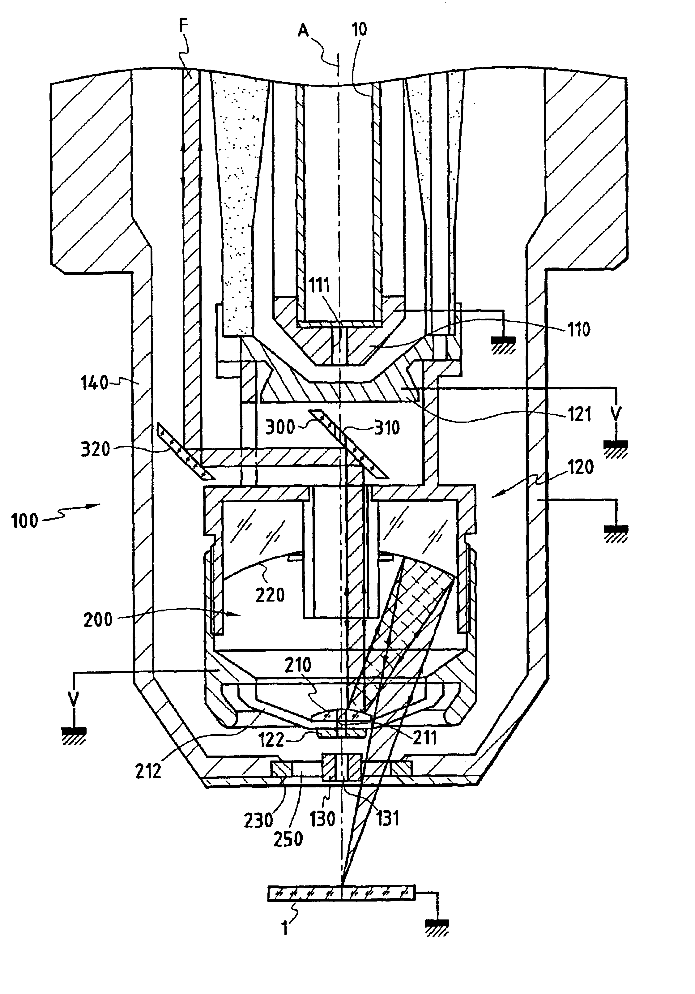
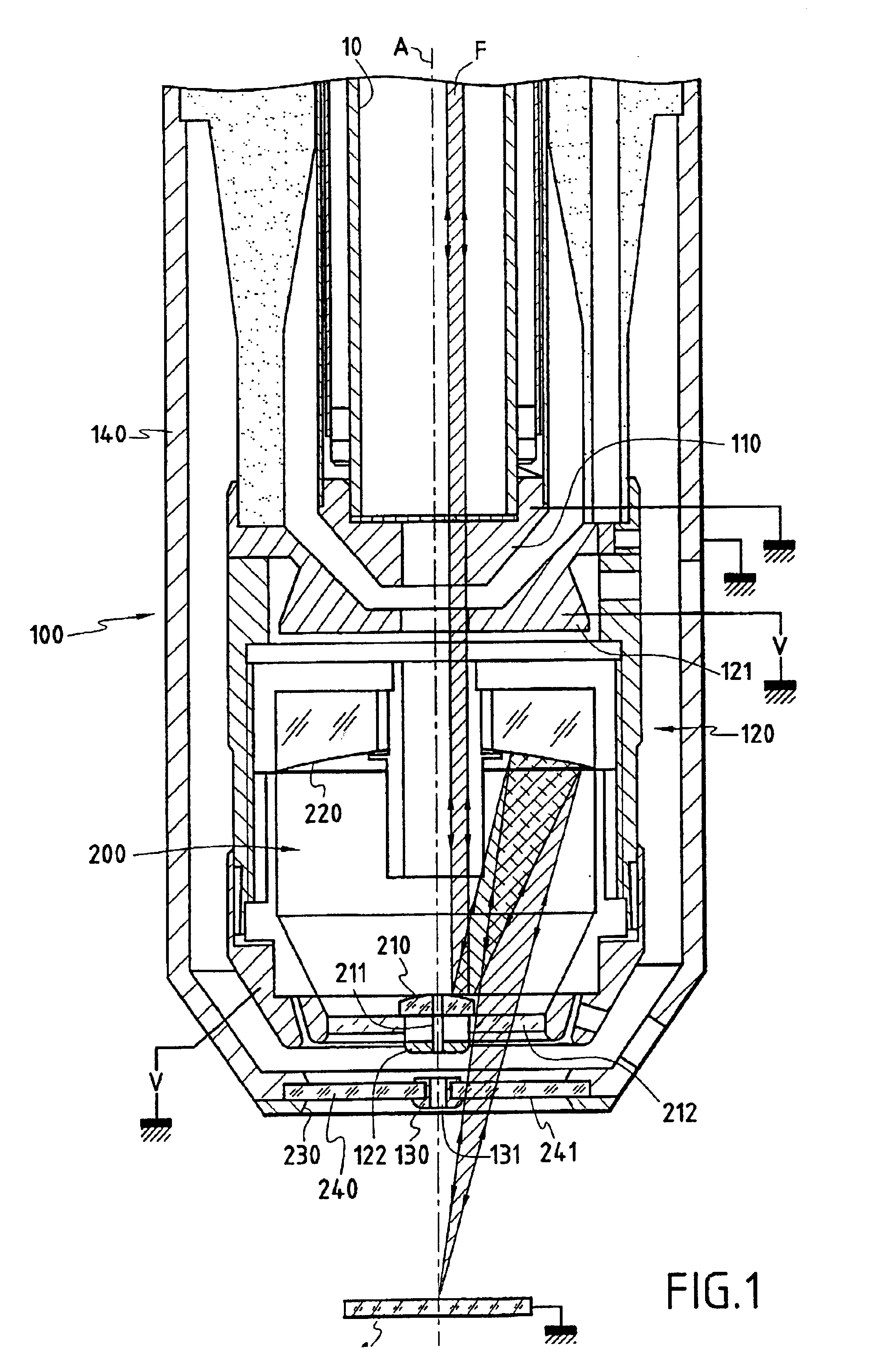
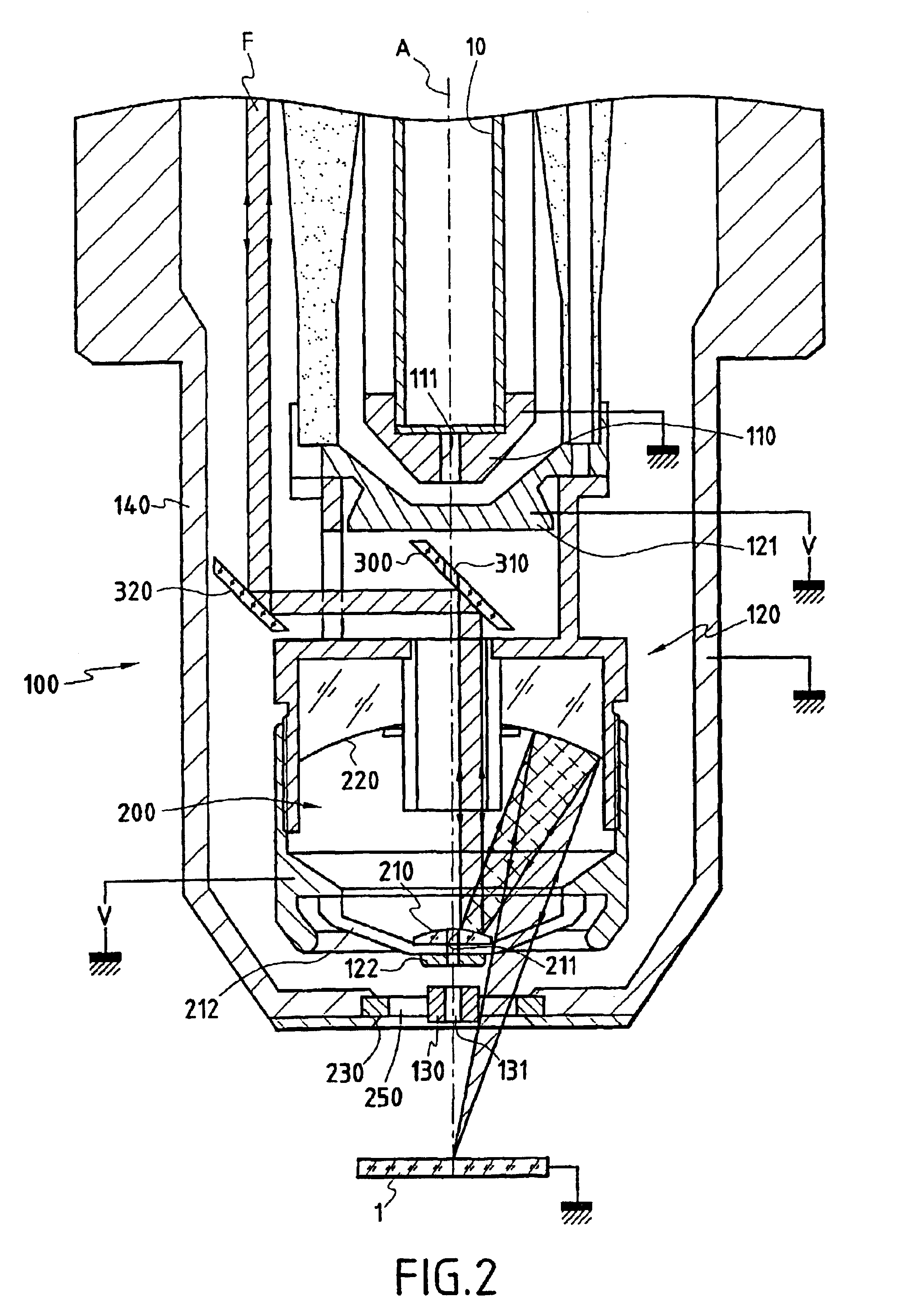
[0039]In FIG. 1, we have partially shown, in section, a particle beam production column for focusing onto an integrated circuit 1. The particle beam axis which coincides with the column axis is identified by reference letter A. Although the column in FIG. 1 applies to all sorts of charged particles, electrons or ions, we shall take below the example of an ion beam.

[0040]Only the downstream part of the column is shown in FIG. 1, the ion source and the means for extracting and conditioning the ion beam which are known per se, not being shown.

[0041]The part of the column shown in FIG. 1 essentially comprises a device 100 for focusing the ion beam onto integrated circuit 1. This device 100 carries three electrodes, specifically an input electrode 110 which is grounded, an intermediate electrode 120 brought to a nonzero potential V which may be positive or negative for example of 20 Kev, and an output electrode 130 also grounded. These electrodes 110, 120, 130 are contained between later...


PUM


Abstract

The invention concerns a column for producing a focused particle beam comprising: a device (100) focusing particles including an output electrode (130) with an output hole (131) for allowing through a particle beam (A); an optical focusing device (200) for simultaneously focusing an optical beam (F) including an output aperture (230). The invention is characterized in that said output aperture (230) is transparent to the optical beam (F), while said output electrode (130) is formed by a metallic insert (130) maintained in said aperture (230) and bored with a central hole (131) forming said output orifice.

Description

CROSS-REFERENCE TO RELATED APPLICATIONS[0001](Not Applicable)STATEMENT REGARDING FEDERALLY SPONSORED RESEARCH OR DEVELOPMENT[0002](Not Applicable)INCORPORATION-BY-REFERENCE OF MATERIAL SUBMITTED ON A COMPACT DISC[0003](Not Applicable)BACKGROUND OF THE INVENTION[0004](1) Field of the Invention[0005]This invention relates that to an optical column for simultaneously focusing an ion beam and a photon beam onto the same region.[0006]The invention is particularly useful in the field of analysis and repair and manufacture of integrated circuits.[0007](2) Description of Related Art[0008]Focused ion beams such as ion or electron beams are currently widely used for various types of integrated circuit analysis and manufacturing operations, notably characterisation, identification, design and failure analysis, depassivation, vapor phase deposition, micro-machining, etc. These operations are performed using a particle beam production column designed to be focused onto the integrated circuit at ...

Claims


Application Information

Patent Timeline
IPC IPC(8): G01N23/00H01J3/14H01J37/22
CPCH01J37/12H01J37/228H01J37/3056H01J37/304G02B17/082H01J2237/31749H01J2237/121H01J2237/2482
Inventor BENAS-SAYAG, GERARDBOUCHET, PATRICKCORBIN, ANTOINESUDRAUD, PIERRE
Owner ORSAY PHYSICS
Why Eureka
Try Eureka