Method for estimating compliance at points along a beam from bending measurements

a bending measurement and compliance technology, applied in the field of new methods, can solve the problems of no optimal method for estimating local, no theoretical support for this use of span functions, and no known approach to account for this non-stationarity of bending spans in the prior art, and achieve the effect of reducing the quality of estimation

Inactive Publication Date: 2006-05-16
KIERSTAT SYST
View PDF3 Cites 16 Cited by
  • Summary
  • Abstract
  • Description
  • Claims
  • Application Information

AI Technical Summary

Benefits of technology

[0069]The new method is able to provide optimal estimates for general bending span configurations, not just for simple cases where span function is easily obtainable by prior art methods. As a necessary part of the method, a general procedure is disclosed for computing span functions.
[0070]The new method optimally estimates local compliance values C along a beam and provides a measure of estimation quality for each estimate.
[0071]The new method provides estimates of local compliance out to the ends of a measured beam, thereby addressing one of the objections of bending measurements. Estimation quality is reduced at points near the beam ends, as one would expect, because fewer compliance measurements are used in the estimation at those points. Also, the amount of the contribution to any measured compliance from a local compliance value near the ends of a tested beam is small. But, for the first time, a measure of estimation quality is provided and a priori information is used to help extend estimation to these previously unavailable segments of the beam.
[0072]The new method can accommodate changes in the bending span as a wood board moves through a machine such as the HCLT. When the leading end of the board enters a bending section of an HCLT, useful data are obtained before all seven supports are engaged. Data are obtained as the bending span number of supports is first 5, then 6, and t

Problems solved by technology

No optimal method exists in the prior art for estimating local compliance (or MOE).
There is no theoretical support for this use of the span function.
In practice, this leads to

Method used


Image

  • Method for estimating compliance at points along a beam from bending measurements
  • Method for estimating compliance at points along a beam from bending measurements
  • Method for estimating compliance at points along a beam from bending measurements

Examples


second alternative embodiment

at Third Points)

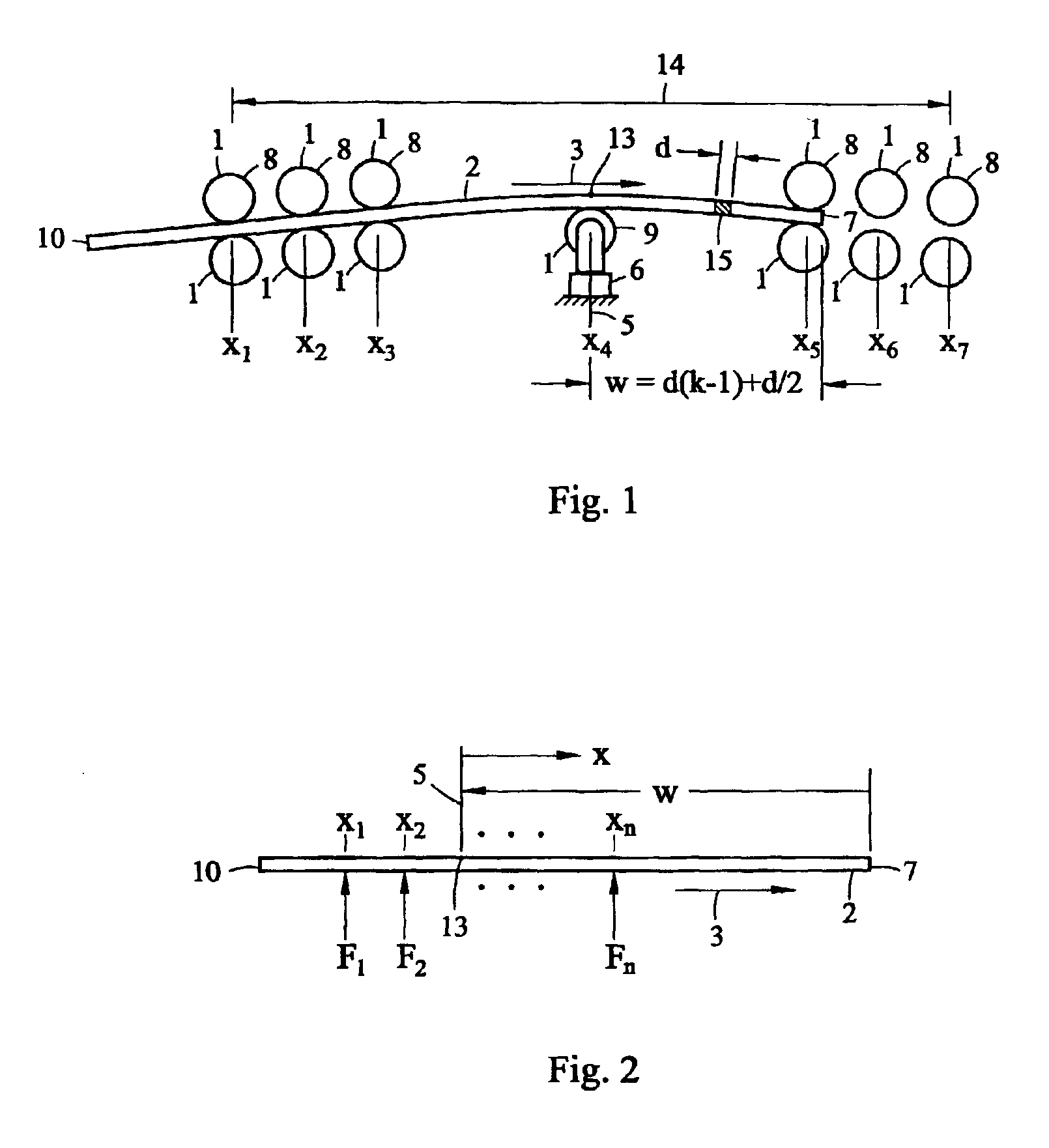
[0293]As another practical example, and to demonstrate another detail, consider a four-support bending span where loads are applied at the “third points” as shown schematically in FIG. 14. This configuration is often used for off-line quality control testing of lumber. A feature of this apparatus is its load-spreading beam 50, which, through fulcrum 51, causes the loads applied by beam 50 to beam 2 to be equal at two support points. As with the first alternative embodiment, deflections and forces are referenced from preload values. The bending span reference 5 is midway in the bending span. In this example, there is no support located at the reference position 5. In FIG. 2, illustrating the general situation, the number of supports is n=4 for this example, and the support locations relative to the reference 5 are x1=−L / 2, x2=−L / 6, x3=L / 6, and x4=L / 2. L is the length of the span so that L=x4−x1. This set of support conditions is indicated by 52 in FIG. 14.

[0294]Two ve...


PUM


Abstract

The inherent smoothing in bending stiffness measurement of wood boards as occurs in the machine grading of lumber can mask the effect of knots and other local characteristics affecting structural value. Improved estimates of local (pointwise) stiffness will be useful in decisions about further processing and use of a tested board. Measured compliance is reciprocally related to measured stiffness and is the convolution of local compliance and a “span function”. Span function is specific to the bending span configuration used and can change during measurement of a board. A general procedure for computing span function, which heretofore has been known only for simple bending spans, is disclosed. A Kalman filter uses this and other available information to optimally estimate local compliance from an observed relationship between local compliance and state variables of a state-space model. Method for linear algebraic determination of local compliance also depends on span functions and is disclosed.

Description

FEDERALLY SPONSORED RESEARCH[0001]In part, this material is based upon work supported by the U.S. Department of Agriculture under Grant No. 00-33610-8896. Any opinions, findings, and conclusions or recommendations expressed in this publication are those of the author and do not necessarily reflect the views of the U.S. Department of Agriculture.FIELD OF INVENTION[0002]This invention relates to new method for processing measurements of bending stiffness (or its reciprocal, compliance) in beams; specifically, the new method may be applied to estimate compliance and hence modulus of elasticity at points along a wood board.REFERENCES CITED IN THE SPECIFICATION[0003]The description of the specification draws freely from references listed here alphabetically by author. When referred to in the specification, a reference is identified by author and date, e.g. (Richburg et al. 1991).[0004]Bechtel, F. K., 1985, “Beam stiffness as a function of pointwise E, with application to machine stress r...

Claims


Application Information

Patent Timeline
IPC IPC(8): G06F17/18
CPCG01N3/20G01N2203/0218G01N2203/021G01N33/46
Inventor BECHTEL, FRIEND K.WANG, NINGHANSHAW, TIMOTHY C.HSU, CHIN S.
Owner KIERSTAT SYST
Why Eureka
Try Eureka