
Method and apparatus for applying fine-grained transforms during placement synthesis interaction

a technology of placement synthesis and transformation, applied in the field of methods and apparatus for applying fine-grained transformations during placement synthesis interaction, can solve the problems of difficult to design logic, difficult to perform these steps in combination at the same time, and inability to achieve the effect of improving design

Inactive Publication Date: 2006-05-16
IBM CORP
View PDF11 Cites 25 Cited by
  • Summary
  • Abstract
  • Description
  • Claims
  • Application Information

AI Technical Summary

Benefits of technology

[0033]With the unique and unobvious aspects of the present invention, the transformational placement and synthesis approach dramatically improves on the conventional techniques that integrate the logic synthesis and placement steps.
[0035]The placement function is decomposed into a set of placement transforms each addressing a specific phase of the placement problem. Each placement step becomes just another transform that changes the design space, in this case the placement of cells. These placement transforms can be freely mixed and matched with the traditional logic synthesis transforms that change the netlist. The accuracy versus runtime tradeoff of these optimizations can be refined as the quality of the placement and netlist data improves in a converging flow.
[0037]Thus, the present invention improves the efficiency and quality of the design process and reduces the burden on system resources.
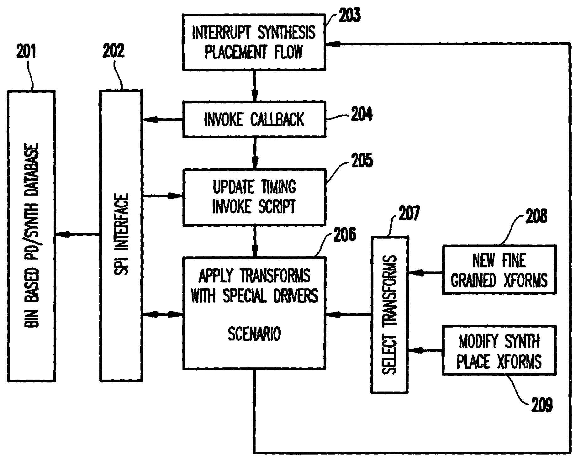
[0041]Hence, the invention performs placement and netlist changes concurrently. The placement program of the invention is incremental in nature and at every step, the invention has the option of intercepting the placement / synthesis flow and experimenting with a range of netlist and placement change transforms for improving the design.

Problems solved by technology

However, performing these steps in combination (at the same time) is problematic.
That is, it is difficult to design the logic since it is unknown where the circuit will be placed on the wafer, and hence connection is uncertain.
For example, the length of the wires is not known and thus the logic design cannot be performed with certainty.
Thus, many assumptions must be made which are typically incorrect.
Most placement algorithms use continuous formulations (i.e., the placement problem is formulated as a continuous mathematical optimization problem) and hence do not lend themselves to discrete optimizations (e.g., such as buffer insertion, pin swapping, etc.) typically used in synthesis.
However, they do not directly take into account feedback from, for example, a timing analyzer because the placement problem is formulated with the objective of minimizing total wire length.
These techniques formulate their problems as continuous optimization problems, and hence do not lend themselves easily to include netlist transformations which are discrete in nature (e.g., buffer insertion, remapping, pin swapping etc.).
Including these objectives directly in the problem formulation leads to expensive optimization algorithms.
However, the runtime of non-linear methods tends to grow quickly with the size of the designs.
These approaches significantly limit the netlist changes that can be made to be able to maintain incrementality in the succeeding placement.
Such a sequential operation leads to inefficiency.
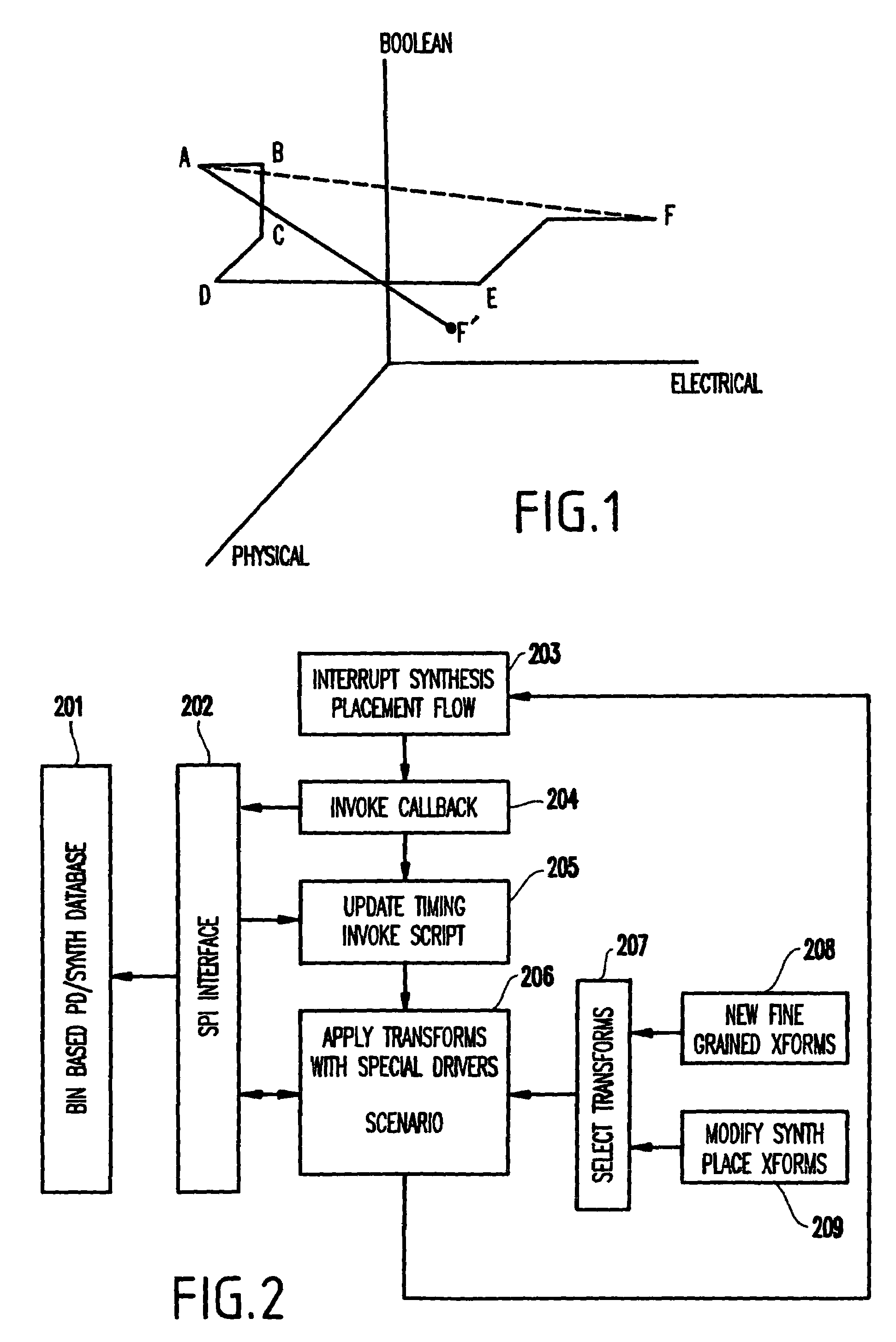
Thus, no single step may optimize the physical, boolean and electrical dimensions, thus moving the design from point A to F in the design space.
Further, a more optimal design point F′ is missed by the optimization process due to the inability to evaluate and optimize the three dimensions at once.
Thus, for example, in the conventional method, a remapping step where a complex gate is broken down into simpler gates will not optimize multiple objectives simultaneously (e.g., by choosing the physical locations of the simpler gates, the sizes and electrical gains of the chosen gates and the topology of boolean function, etc.).
Moreover, this first conventional method is unable to use a partially placed and synthesized design as the starting point.
Hence, an incremental netlist and physical design improvement is not possible in this method.
Finally, this first conventional method is not based on the infrastructure of bins, and therefore is unable to allow for quick logic redesign with placement.
Moreover, there is no ability to externally control the logic / placement redesign using scenarios.
However, this second method is problematic in that there are no placement and netlist changes (synthesis) performed together in the form of fine-grained transforms.
Moreover, there is no timing verification which is internal to both the placement and synthesis algorithms leading to a converging placement / netlist change flow.
Moreover, the step of making netlist changes followed by ECO placement is inefficient and unnecessary.
However, this third conventional method is deficient in that placement and netlist changes are not performed concurrently.
Further, the placement program is not incremental in nature and there is no option, at every step, of intercepting the placement program and experimenting with a range of netlist change transforms (that are more effective than net weighting), for improving the design.
However, this fourth conventional method is problematic in that it performs only placement changes.
Hence, timing is not constructively improved by concurrently applying both placement and netlist changes.
Thus, the conventional techniques have serious drawbacks which lead to inefficiency and complex, time-consuming computations and expenditure of system resources.

Method used


Image

  • Method and apparatus for applying fine-grained transforms during placement synthesis interaction
  • Method and apparatus for applying fine-grained transforms during placement synthesis interaction
  • Method and apparatus for applying fine-grained transforms during placement synthesis interaction

Examples


first embodiment

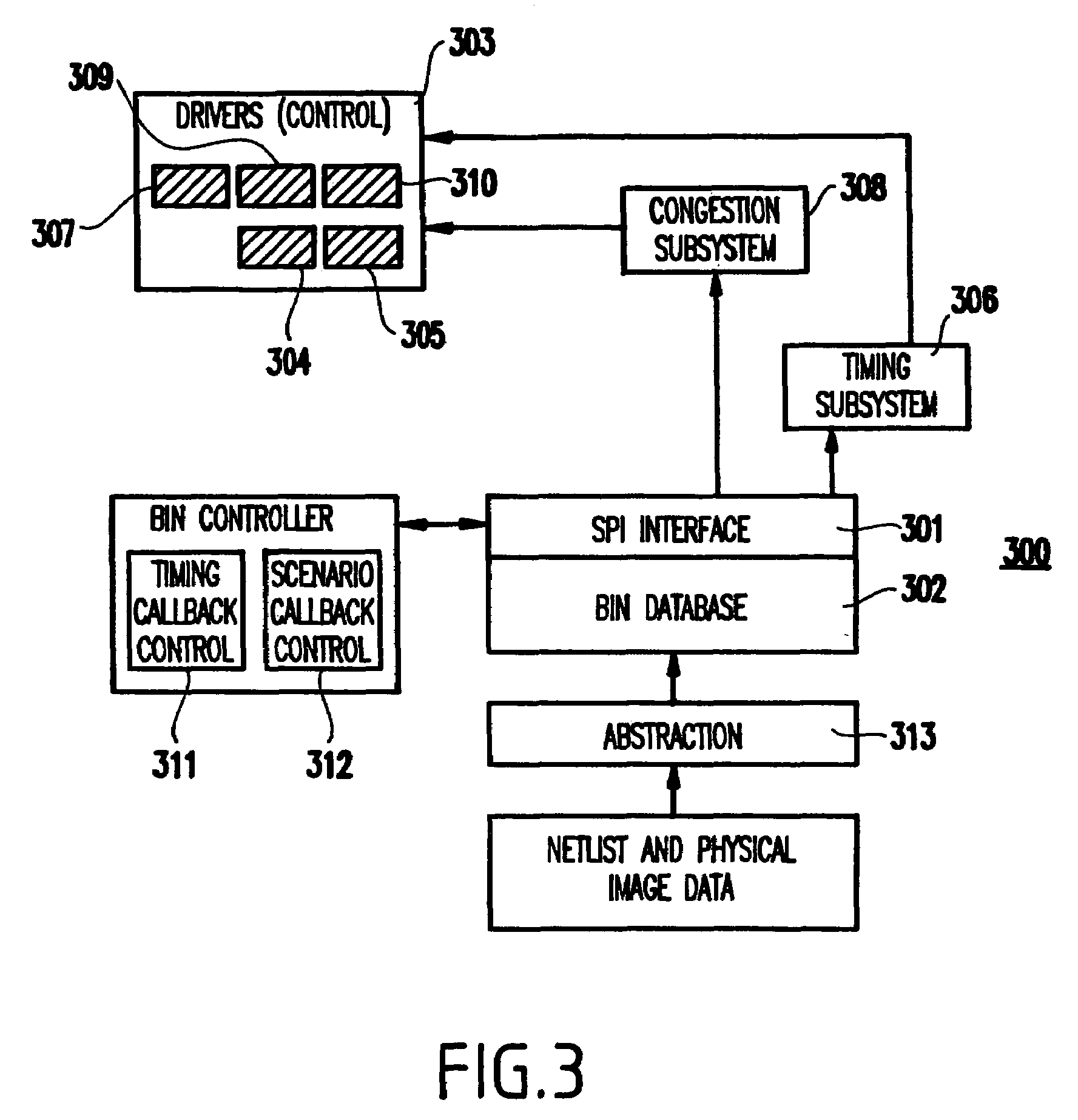
[0051]Referring to FIGS. 2–7, a first embodiment of the present invention will be described below.

[0052]As mentioned above, the invention examines a plurality of domains concurrently in finding an optimum design. That is, the inventive transformational placement and synthesis approach creates a sequence of more and less granular placement and netlist modification transforms (e.g., steps which change the design space from one point to another; there are boolean transforms, electrical transforms, and placement / physical transforms) thereby to create a converging design closure process, starting from just a netlist without initial placement.

[0053]The placement function is decomposed into a set of placement transforms each addressing a specific phase of the placement problem. Each placement step becomes just another transform that changes the design space, in this case the placement of cells. These placement transforms can be freely mixed and matched with the traditional logic synthesis ...


PUM


Abstract

A method (and system) of applying transforms for modifying a plurality of domains concurrently in a design space, includes creating a sequence of more and less granular placement and netlist modification transforms. A converging design process flow is created by a flexible mechanism in which a select combination of fine-grained transforms are applied to optimize the netlist and placement of a design.

Description

BACKGROUND OF THE INVENTION[0001]1. Field of the Invention[0002]The present invention relates to a novel infrastructure and method to seamlessly integrate logic synthesis and physical placement through a transformational approach, and more specifically to a method and apparatus for applying fine-grained transformations during placement synthesis interaction.[0003]2. Description of the Related Art[0004]Typically, in chip design, several steps are performed in sequence including a high level synthesis step for creating a register transfer level representation of the design, a logic synthesis step for automatically creating a circuit from the register transfer level description, a placement step to place the circuits on the chip, a routing step for routing the placed design and finally fabrication can be performed. Traditionally, logic synthesis and placement have been two separate steps.[0005]Recently, attempts to combine these two design steps (logic synthesis and placement) have bee...

Claims


Application Information

Patent Timeline
Patent Type & Authority Patents(United States)
IPC IPC(8): G06F17/10G06F15/18G06F7/60G06G7/00G06N3/00
CPCG06F17/5072G06F17/5045G06F30/30G06F30/392
Inventor CHAKRABORTY, KANADDONATH, WILM ERNSTKUDVA, PRABHAKAR NANDAVARREDDY, LAKSHMI NARASIMHASTOK, LEONSULLIVAN, ANDREW JAMESVILLARRUBIA, PAUL GERARD
Owner IBM CORP
Learn More