
Methods for low emission, controlled temperature combustion in engines which utilize late direct cylinder injection of fuel

a technology of direct cylinder injection and combustion process, which is applied in the direction of electric control, machines/engines, instruments, etc., can solve the problem of more difficult to avoid temporary fuel levels in excess of desired fuel/oxygen ratio, and achieve the effect of minimizing harmful emissions, reducing harmful emissions, and increasing pm levels

Inactive Publication Date: 2006-05-23
ENVIRONMENTAL PROTECTION AGENCY US
View PDF15 Cites 50 Cited by
  • Summary
  • Abstract
  • Description
  • Claims
  • Application Information

AI Technical Summary

Benefits of technology

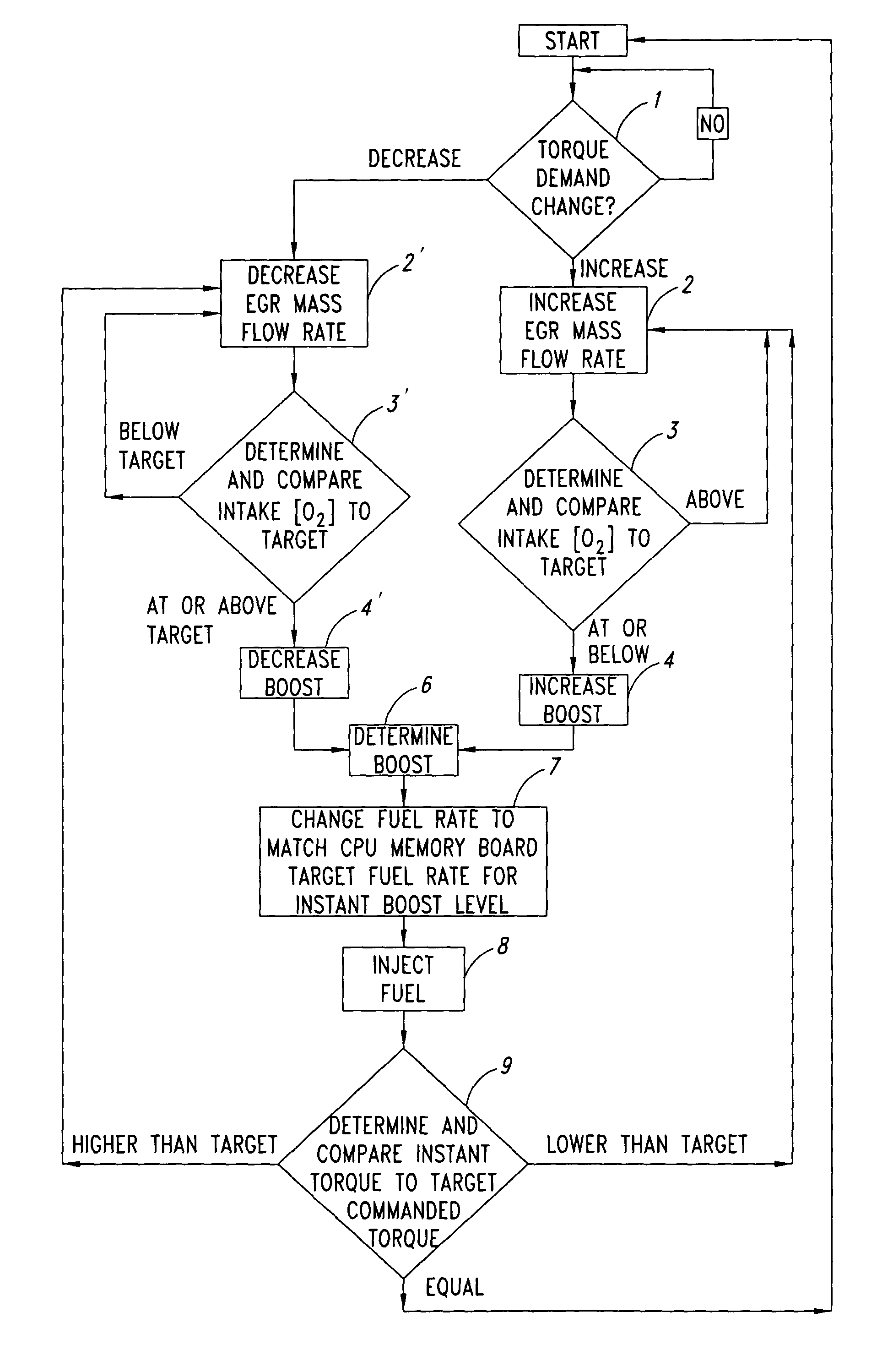
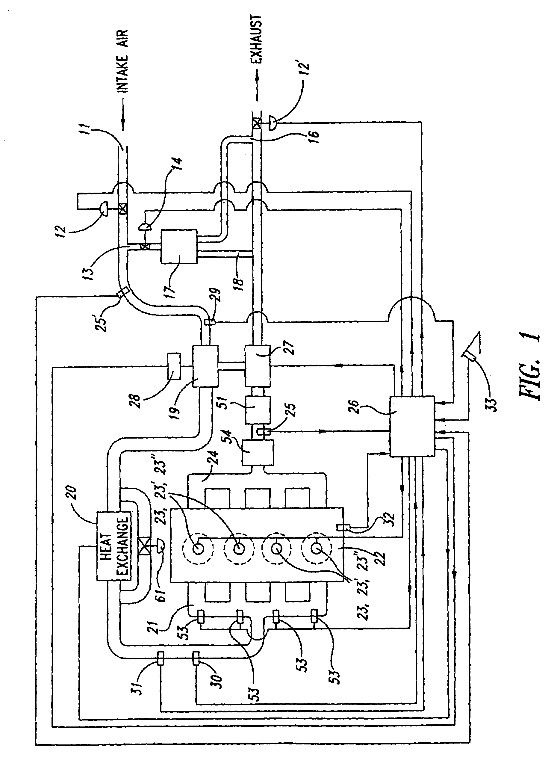
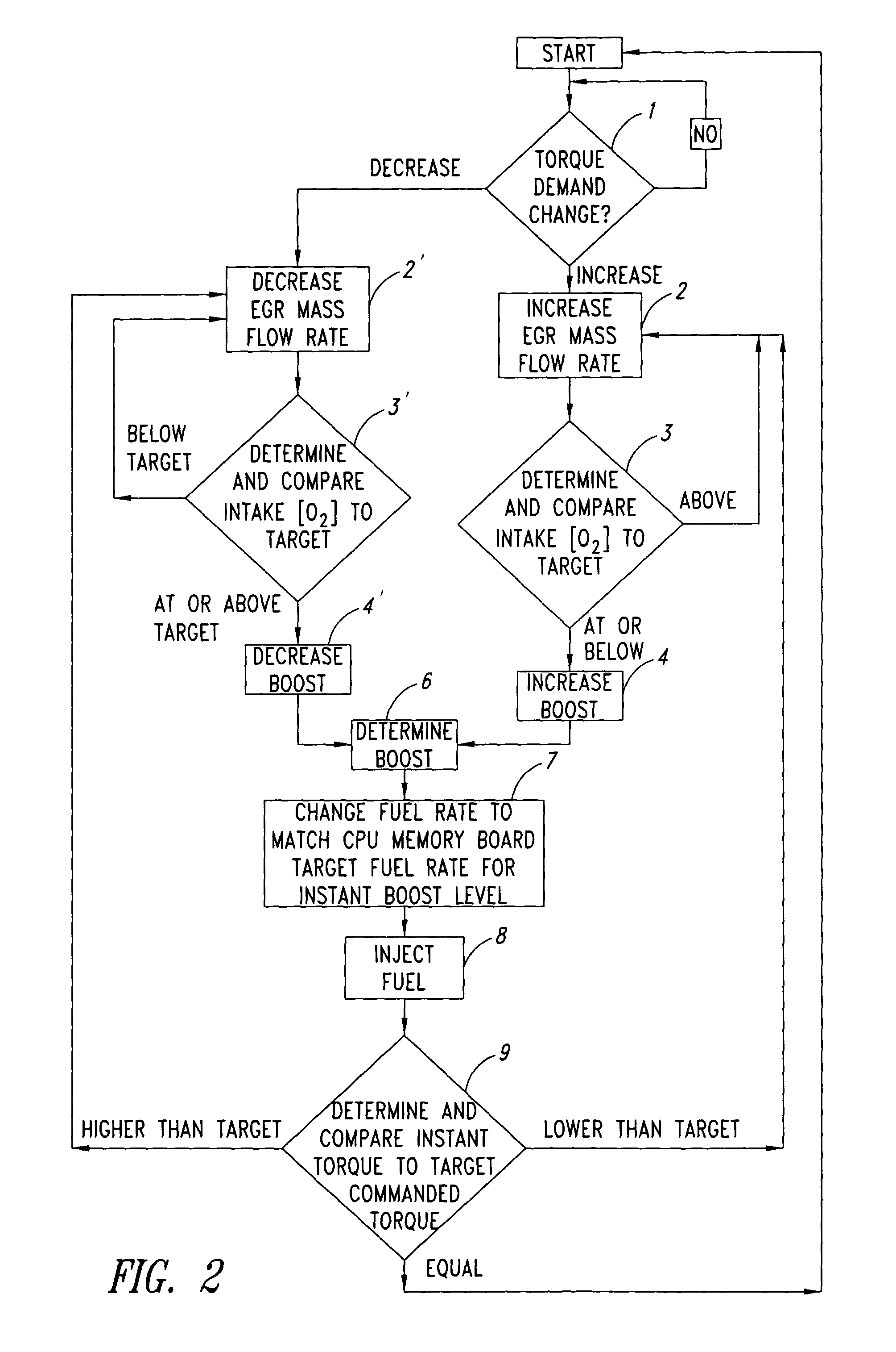
[0014]The present invention provides an effective method for close control and adjustment of in-cylinder oxygen concentration levels together with boost adjustments in such a way as to minimize harmful emissions during transients in engines which utilize late direct cylinder injection of fuel. In one aspect of this invention, EGR flow rates are adjusted by means of an EGR control valve in a closed loop, linked fashion together with boost pressure changes during transients, to maintain intake charge-air oxygen concentration and boost levels preferably within critical ranges for controlled temperature, low emission combustion at all times.
[0015]Furthermore, as another aspect of this invention, in order to minimize harmful emissions during rapid transient changes in operating conditions (e.g. vehicle acceleration), corresponding increases in fuel feed into the cylinder are constrained to wait for or follow with boost adjustments. In this manner, during acceleration, increase in boost pressure and charge-air density enable the increase in fuel feed to respond to the driver's demand for more torque. Prior art diesel engines, to the contrary, have fuel feed adjustments take place prior to (i.e. “lead”) the adjustments in boost. However, the inventor has found that if fuel feed increases lead the boost increases, it is more difficult to avoid having temporary fuel levels in excess of desired fuel / oxygen ratios, with the result of increased PM levels from insufficient oxygen for good, complete combustion. This problem may most easily be avoided by having fuel feed adjustments wait for or follow boost changes instead, determining and injecting a fuel quantity responsive to the instant pressure of the boosted charge-air being taken into the cylinder for the particular combustion cycle.

Problems solved by technology

However, the inventor has found that if fuel feed increases lead the boost increases, it is more difficult to avoid having temporary fuel levels in excess of desired fuel / oxygen ratios, with the result of increased PM levels from insufficient oxygen for good, complete combustion.

Method used


Image

  • Methods for low emission, controlled temperature combustion in engines which utilize late direct cylinder injection of fuel
  • Methods for low emission, controlled temperature combustion in engines which utilize late direct cylinder injection of fuel
  • Methods for low emission, controlled temperature combustion in engines which utilize late direct cylinder injection of fuel

Examples


Embodiment Construction

The Importance of Boost Control for Controlled Temperature Combustion

[0019]As discussed in the parent application hereto (U.S. patent application Ser. No. 10 / 214,229), for a given quantity of fuel to be burned, assuming adiabatic combustion, the final combustion temperature, T3, is in the form of T3=T2+Hc / Cv (where T2 is the final compression temperature, Hc=heat released from combustion of the fuel, and Cv is the total heat capacity of the charge-air fuel mixture, i.e., the mass of the mixture times the specific heat capacity). A goal to minimize NOx formation is to lower and control T3 (to 2000° Kelvin, for example). Since for a given quantity of fuel burned, Hc is fixed, the only variable to control T3 is Cv. If Cv is large, T3 will be lower.

[0020]Given the foregoing, one known strategy for lowering and controlling peak combustion temperatures is by adjusting the heat capacity of the charge-air fuel mixture. However, given the above equations, for T3 to be controlled to a stable ...


PUM


Abstract

A method is provided for close control and adjustment of in-cylinder oxygen concentration levels together with boost adjustments to minimize harmful emissions during transients in engines which utilize late direct cylinder injection of fuel. EGR flow rates are adjusted in a closed loop, linked fashion together with boost pressure changes during transients, to maintain intake charge-air oxygen concentration and boost levels within critical ranges for controlled temperature, low emission combustion. Changes in fuel feed into the cylinder are made to wait for or follow changes in the boost level of charge-air into the cylinder for combustion. Temporary fuel levels are not allowed to exceed desired fuel / oxygen ratios during transients, by controlling fuel feed responsive to the level of boost of charge-air being taken into the cylinder for combustion.

Description

CROSS REFERENCE TO RELATED APPLICATION[0001]This application is a continuation-in-part of U.S. patent application Ser. No. 10 / 241,229 filed Sep. 10, 2002, now U.S. Pat. No. 6,845,987 which application, in its entirety, is incorporated herein by reference.BACKGROUND OF THE INVENTION[0002]The present invention relates to methods for controlling combustion processes in engines that utilize late direct cylinder injection of fuel, such as diesel engines, to reduce harmful emissions produced thereby. For ease of reference, this application may at times simplistically refer only to diesel engines, however, the scope of the invention equally applies to other engines that utilize late direct cylinder injection of fuel as well.[0003]Internal combustion engines which utilize late direct cylinder injection of fuel, such as conventional diesel engines, emit harmful pollutants such as nitrogen oxides (NOx) and particulate matter (PM) substantially in excess of acceptable environmental levels. Nev...

Claims


Application Information

Patent Timeline
IPC IPC(8): F02D23/00F02B23/00F02B31/00F02B5/00F02B37/00F01N3/035F01N13/02F01P3/12F01P3/20F01P5/02F01P7/14F01P7/16F02B1/12F02B37/007F02B37/013F02B37/10F02B37/14F02B39/10F02D21/08F02D23/02F02D35/02F02D41/00F02D41/02F02D41/04F02D41/14F02D41/30F02D43/00F02D45/00F02M25/07F16J15/34F16J15/42G01M99/00
CPCF01N3/035F01N13/009F02B1/12F02B29/0418F02B37/10F02B37/14F02B39/10F02D41/0007F02D41/3035F16J15/3448F16J15/42F02D35/026F01N2340/06F01N2430/06F02D41/0052F02D41/144F02D41/1454F02D2200/0406F02M25/0711F02M25/0718F02M25/0727F02M25/074F02M25/0755Y02T10/146Y02T10/144F01N2340/04F02M26/46F02M26/08F02M26/15F02M26/23F02M26/35Y02T10/12F02D41/30F02D41/38F02B33/44F02D35/02
Inventor GRAY, JR., CHARLES L.
Owner ENVIRONMENTAL PROTECTION AGENCY US
Learn More