Method for detecting wear in a brake or a clutch

a technology of brakes and clutches, applied in the direction of instruments, structural/machine measurement, force/torque/work measurement, etc., can solve the problems of air gap becoming larger, wear generally occurring, and the inductance of electrical excitable coils decreasing, so as to reduce the cost of wear detection, and improve the inductance of coils.

Active Publication Date: 2006-05-23
SIEMENS AG
View PDF12 Cites 9 Cited by
  • Summary
  • Abstract
  • Description
  • Claims
  • Application Information

AI Technical Summary

Benefits of technology

[0021]In a preferred embodiment of the device for detecting wear in a frictionally locking clutch or a frictionally locking brake, at least one element which is involved in the frictional locking comprises ferromagnetic material. Parts which are affected by the wear, such as a friction surface are preferably located in the region of the airgap of a magnetic circuit which is influenced by the excitable coil. This magnetic circuit is then influenced in the region of the airgap in particular if the parts which are subjected to wear have a ferromagnetic material. The greater the change in the inductance of the coil when wear occurs, the simpler the determination of the wear.
[0022]In another preferred embodiment of the device for detecting wear in a frictionally locking clutch or a frictionally locking brake, the electrically excitable coil is excited at least by means of a voltage jump or by means of an alternating voltage. A changing electrical current through the coil is necessary to determine wear. A change in current occurs when there is a change in the ...

Problems solved by technology

This wear generally occurs in frictionally locking brakes or frictionally locking clutches with an electrically excitable coil in the region between an airgap of a magnet...

Method used


Image

  • Method for detecting wear in a brake or a clutch
  • Method for detecting wear in a brake or a clutch
  • Method for detecting wear in a brake or a clutch

Examples


Embodiment Construction

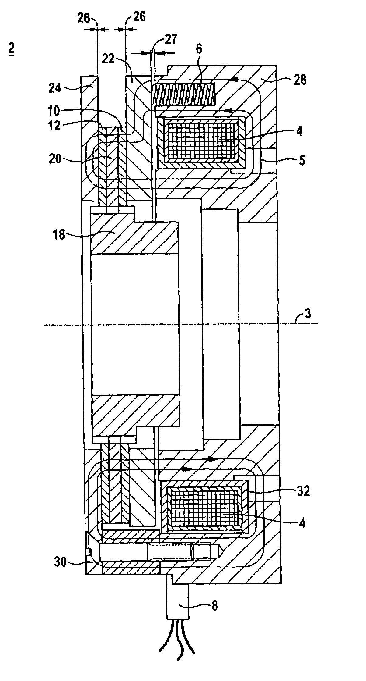
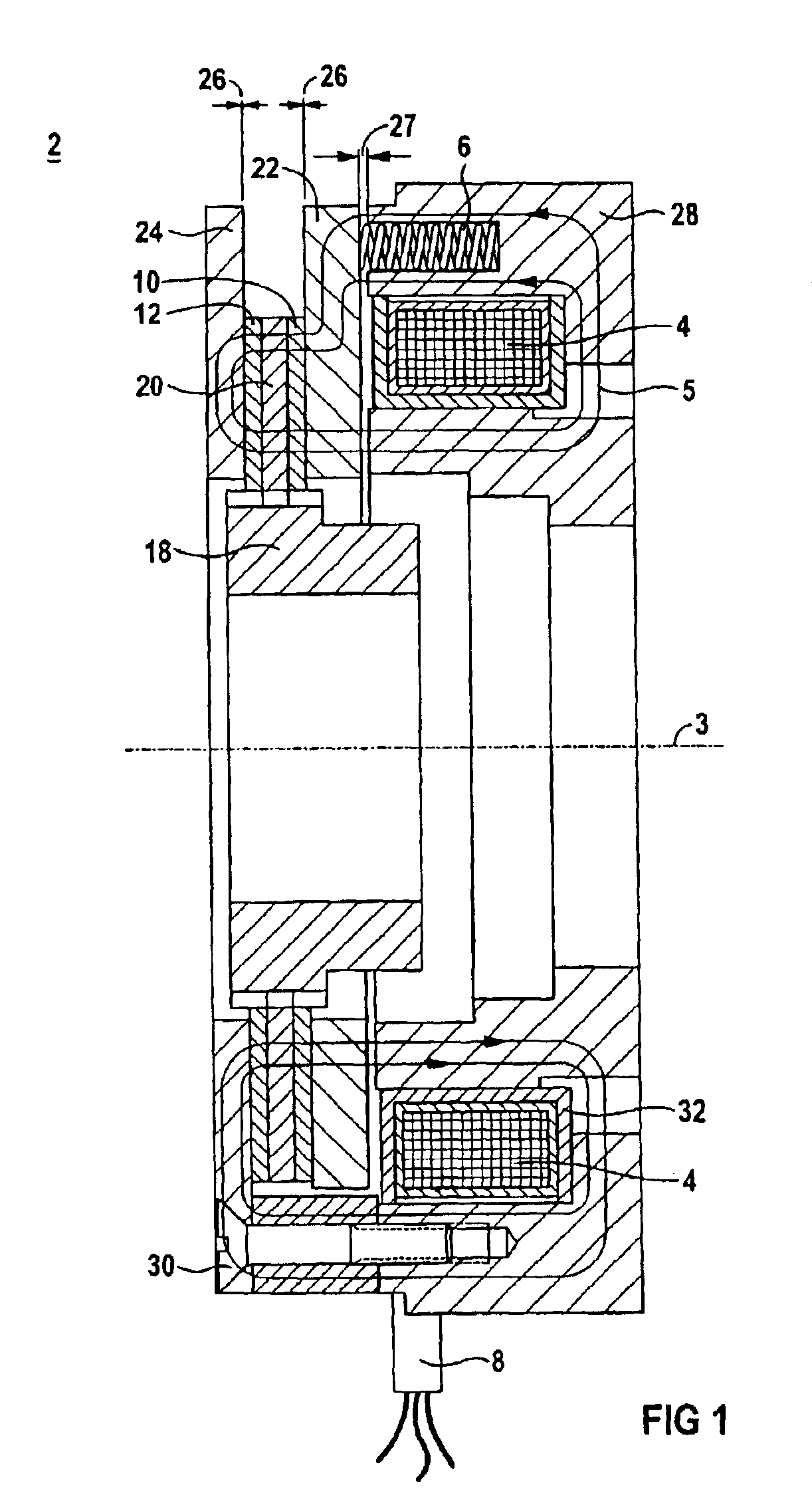
[0037]FIG. 1 shows a spring pressure brake 2. It has a fixed element such as an armature 22 and at least one element which can move in rotation about an axis 3, here a driver 18 and a friction disk 20. The armature 22 is connected via a spring 6 to a magnet housing 28. Within the magnet housing there is an electrically excitable coil 4 in a coil housing 32. The coil 4 can be excited by means of a coil terminal 8 so that a magnetic field is formed in the excited state. A magnet flux 5 is represented by lines. Between the armature 22 and the magnet housing 28 is an airgap 27. This airgap 27 occurs when the spring 6 presses the armature 22 against the friction disk 20, the friction disk 20 having a brake lining 10 and 12. The brake lining 10 is then located in a frictionally locking connection with the armature 22, whereas the brake lining 12 is in a frictionally locking connection with the friction plate 24, which is also fixed like the armature 22. If the brake is opened, an airgap 2...


PUM


Abstract

The invention relates to a method for detecting wear in a frictionally locking clutch (50) or a frictionally locking brake (2, 40), the clutch (50) or the brake (2, 40) having at least one electrically excitable coil (4) and at least one element (20, 21, 23) which can move in rotation about an axis (3), to bring about frictional locking with at least one corresponding mating element (22, 28, 54), at least the element (20, 21, 23) which can move in rotation or the corresponding mating element (22, 54) being axially movable, and it being possible to form an airgap (26). The wear (46) can be inferred by virtue of the fact that the electric current is measured by the electrically excitable coil (4), evaluated and the evaluation compared with at least one reference value.

Description

[0001]The invention relates to a method for detecting wear in a frictionally locking clutch or a frictionally locking brake.BACKGROUND OF THE INVENTION[0002]Clutches and brakes are known which use frictionally locking connections as a functional principle. These brakes and / or clutches have, for example, at least one electrically excitable coil, and at least one element which can move in rotation about an axis, to bring about frictional locking with a corresponding mating element. In this context, the element which can move in rotation or else the corresponding mating element can move axially. The clutch and brake respectively transmit forces and torques, the brake reducing the kinetic energy of at least one moving body by means of a frictionally locking connection to at least one nonmoving body, and the clutch coupling to one another, and decoupling, at least two movable bodies for their common movement.[0003]Brakes may, for example, be permanent magnet brakes. In this context, the ...

Claims


Application Information

Patent Timeline
IPC IPC(8): G01M19/00G01R27/26G01M99/00G01L5/28G01M13/02
CPCG01M13/022G01L5/28
Inventor GIESSLER, FOLKE
Owner SIEMENS AG
Why Eureka
Try Eureka