
Reversible grooved tubes for heat exchangers

a heat exchanger and groove technology, applied in the field of heat exchanger tubes, can solve the problems that skilled in the art already face considerable difficulties in extracting the quintessence of the prior art, and achieve the effects of reducing the weight of the meter, reducing the cost of material, and ensuring the effect of quality

Inactive Publication Date: 2006-05-23
TREFIMETAUX SA
View PDF16 Cites 15 Cited by
  • Summary
  • Abstract
  • Description
  • Claims
  • Application Information

AI Technical Summary

Benefits of technology

[0035]so as to obtain simultaneously a high heat exchange coefficient both in evaporation and condensation, a low pressure loss and the lightest possible tube, without inducing an additional cost in relation to specific tubes for evaporation or condensation.
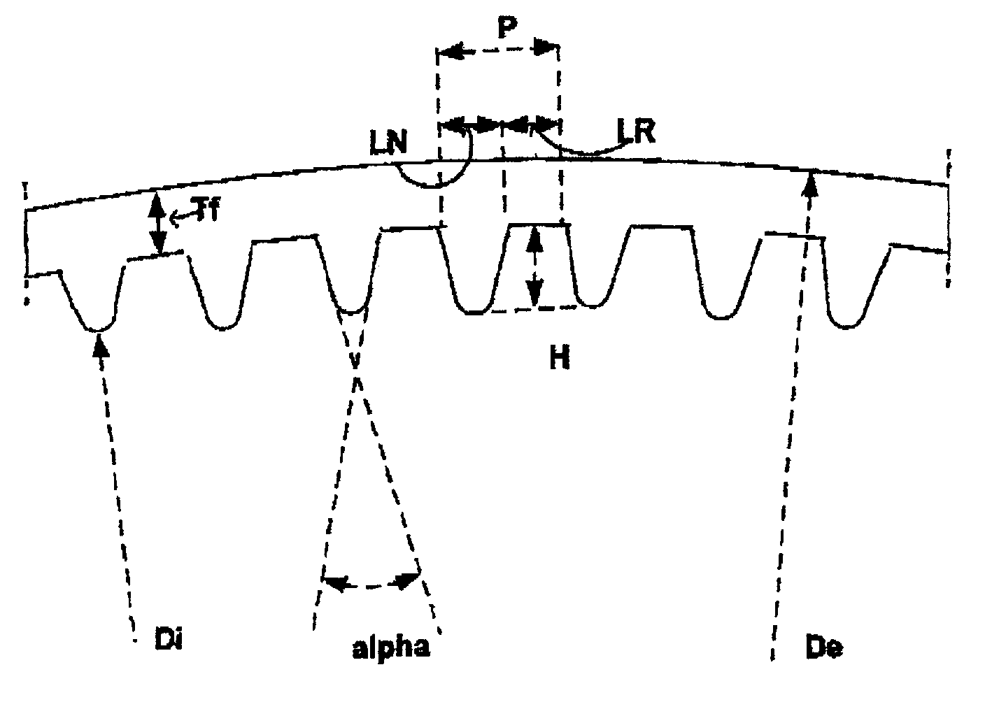
[0042]It was observed on a tube of diameter De of 12 mm that a number of ribs N of 98 guarantees a high thermal performance of the exchanger in evaporation and condensation.
[0044]for values of H greater than 0.40 mm, a lower technical feasibility was observed, since it is not easy to manufacture very high ribs, and an increase in the pressure loss was also observed,
[0048]Firstly, a low apex angle value α is preferable to improve the heat transfer performance to reduce the pressure loss and reduce the tube weight / m. The lowest angle α is obtained with trapezoidal ribbing.
[0051]Relating to the thickness Tf of the tube at the bottom of the groove, it may vary as a function of the diameter De, so as to obtain, at the same time, sufficient mechanical properties, particularly resistance to internal pressure, maximum material preservation, and therefore an optimised material cost, and the lowest possible weight per metre. This thickness Tf is 0.28 mm for a tube of diameter De of 9.55 mm, and 0.35 mm for a tube of diameter De of 12.7 mm.
[0052]All these means make it possible to define a selection of tubes, specific tubes particularly suitable for exchangers with phase transition coolants, so as to obtain simultaneously a high heat exchange coefficient in evaporation and condensation, a low pressure loss and the lightest possible tube.

Problems solved by technology

secondly, the characteristics relating to pressure losses, low pressure losses enabling the use of pumps or compressors of lower power, size and cost,
Definitively, those skilled in the art already encounter considerable difficulties in extracting the quintessence of the prior art, from such a wide range of sometimes contradictory data.

Method used


Image

  • Reversible grooved tubes for heat exchangers
  • Reversible grooved tubes for heat exchangers
  • Reversible grooved tubes for heat exchangers

Examples


examples of embodiments

[0097]I—Tube Manufacture

[0098]The tests were conducted on copper tubes with an outer diameter of 8.0 mm or 9.52 mm.

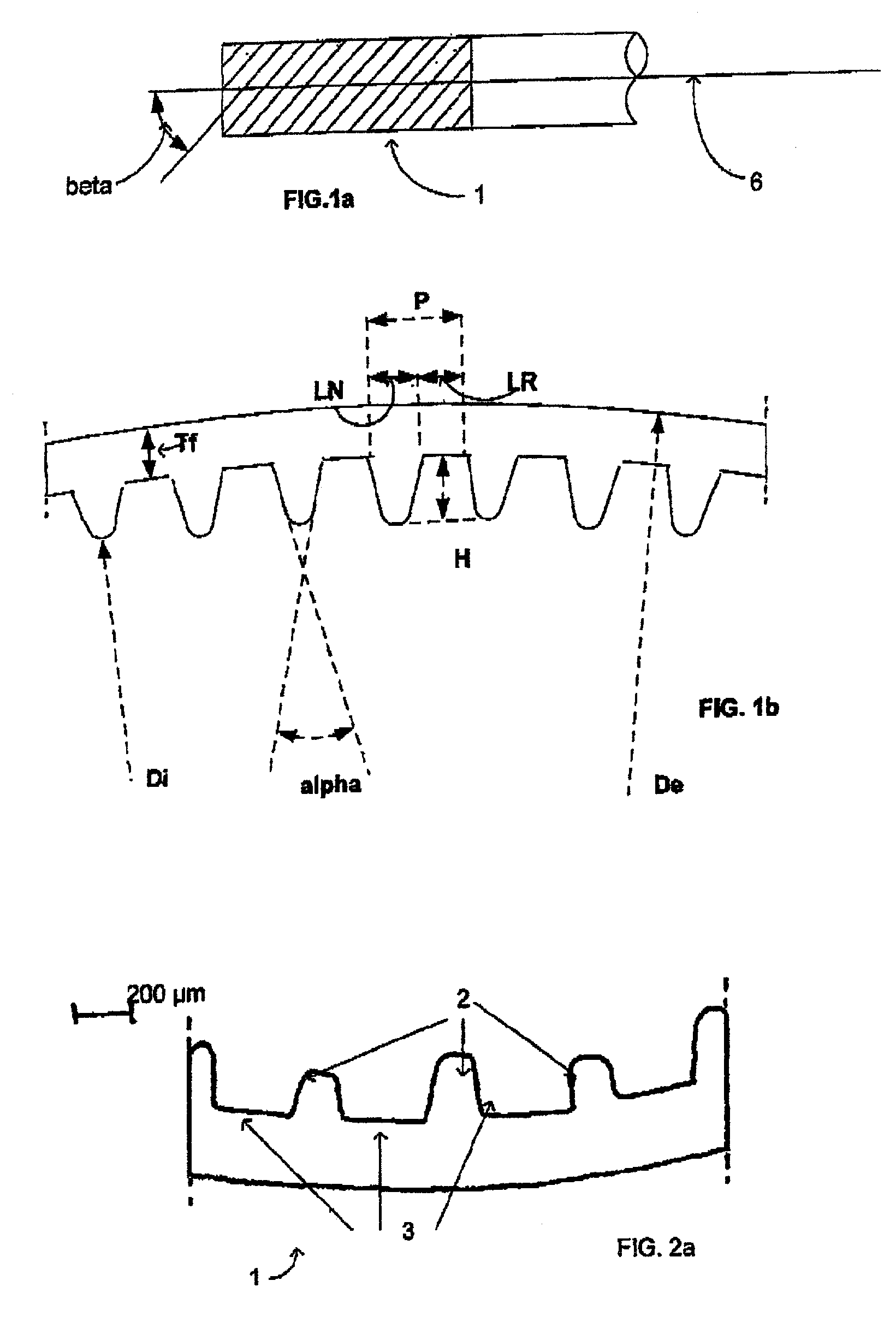
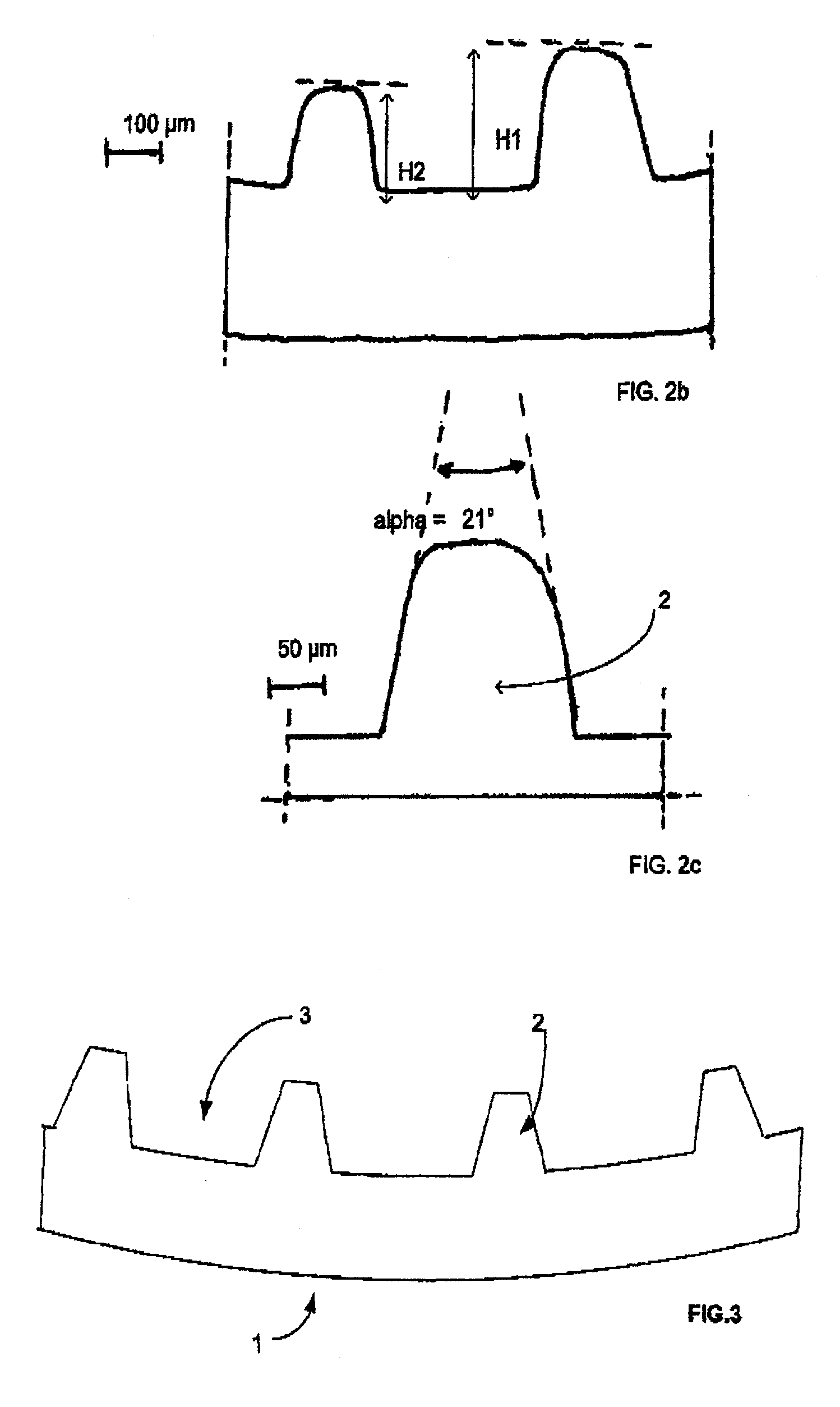
[0099]The tube “E” according to the invention was manufactured according to FIGS. 2a to 2c with a diameter De of 8.0 mm, and according to FIG. 3 with a diameter De of 9.52 mm, along with the comparative tubes “S” or smooth, “C”, “D”, which comprise a high helical angle β (at least equal to 20°), intended for condensation according to the prior art, and comparative tubes “A” and “B”, which comprise a high apex angle α (at least equal to 40°) and a low helical angle β (not more than 18°), intended for evaporation according to the prior art.

[0100]Tubes E, A, B, C were manufactured by grooving a smooth copper tube—tube S, while tube D was manufactured by means of flat grooving of a metal strip followed by formation of a welded tube.

[0101]A number of tests were conducted on copper tubes with an outer diameter De of 9.52 mm. These tubes show the following characteristics:

[010...


PUM

PropertyMeasurementUnit
outer diameteraaaaaaaaaa
heightaaaaaaaaaa

Abstract

Grooved metal tubes (1), of outer diameter De, the tubes being grooved internally with N helical ribs (2) of an apex angle α, height H, base width LN and helical angle β, two consecutive ribs being separated by a flat-bottomed groove (3) of width LR, with a pitch P equal to LR+LN. These tubes are characterised in that,a) De is between 4 and 20 mm,b) the number N of ribs ranges from 46 to 98,c) the rib height H ranges from 0.18 mm to 0.40 mm,d) the apex angle α ranges from 15° to 30°,e) the helical angle β ranges from 18° to 35°. These tubes make it possible to simultaneously obtain a high heat exchange coefficient in evaporation and condensation and a low pressure loss.

Description

FIELD OF THE INVENTION[0001]The invention relates to the field of heat exchanger tubes, and more specifically the field of heat exchangers operating in evaporation / condensation and in reversible mode.DESCRIPTION OF RELATED ART[0002]A large number of documents disclosing the geometry of grooved tubes used in heat exchangers are known.[0003]For example, it is possible to mention the patent application EP-A2-0 148 609 which discloses triangular or trapezoidal grooved tubes comprising the following characteristics:[0004]an H / Di ratio between 0.02 and 0.03, where H refers to the depth of the grooves (or height of the ribbing), and Di the inner diameter of the grooved tube,[0005]a helical angle β with reference to the tube axis between 7 and 30°,[0006]an S / H ratio between 0.15 and 0.40, where S refers to the cross-section of the groove,[0007]an apex angle α of the ribbing between 30 and 60°.[0008]These tube characteristics are suitable for phase transition fluids, the tube performances be...

Claims


Application Information

Patent Timeline
Patent Type & Authority Patents(United States)
IPC IPC(8): F28F1/36F28F1/00B21C37/15F25B39/00F28F1/40F28F21/08
CPCF28F1/40B21C37/15F25B39/00F28F1/36F28F21/00
Inventor LETERRIBLE, PASCALAVANAN, NICOLAS
Owner TREFIMETAUX SA
Learn More