
MR-compatible devices

a technology of compatible devices and medical devices, applied in the field of medical devices delivery methods, can solve the problems of limited accuracy of procedures, limited surface accuracy, and limited technique,

Inactive Publication Date: 2006-05-23
STANDFORD UNIV +2
View PDF119 Cites 592 Cited by
  • Summary
  • Abstract
  • Description
  • Claims
  • Application Information

AI Technical Summary

Problems solved by technology

While endoscopic, arthroscopic, and endovascular therapies have already produced significant advances in health care, these techniques ultimately suffer from the same limitation.
This limitation is that the accuracy of the procedure is “surface limited” by what the surgeon can either see through the device itself or otherwise visualize (as by optical fibers) during the course of the procedure.
That is, the visually observable field of operation is quite small and limited to those surfaces (especially external surfaces of biological masses such as organs and other tissue) observable by visible radiation, due to the optical limitations of the viewing mechanism.
An important issue in either approach is the accuracy of the navigational process used to direct the movement of the drug delivery device.
Without removal of the magnetic tip from the catheter, whole body magnetic forces might be produced on it by the field of the MR imaging system, and these could cause undesired movement of the catheter that it has just steered into place within the body.
At the same time, the limited distribution of drug injected from a single catheter tip presents other problems.
Delivery of a drug from a single point source may also limit the distribution of the drug by decreasing the effective radius of penetration of the drug agent into the surrounding tissue receptor population.
X-ray imaging, such as X-ray fluoroscopy, is a possible method of providing a view of the procedural area, but X-ray exposure for any extended period of time is itself harmful to the patient.
Fiber optic viewing of the area does not provide any harmful radiation to the patient, but the fiber optics may take up too large a space to provide both the light necessary for viewing and a path for return of the light, and does not permit beyond the surface imaging (that is, only the surfaces of internal objects may be viewed from the position where the fiber optic device is located).

Method used


Image

  • MR-compatible devices
  • MR-compatible devices
  • MR-compatible devices

Examples


Embodiment Construction

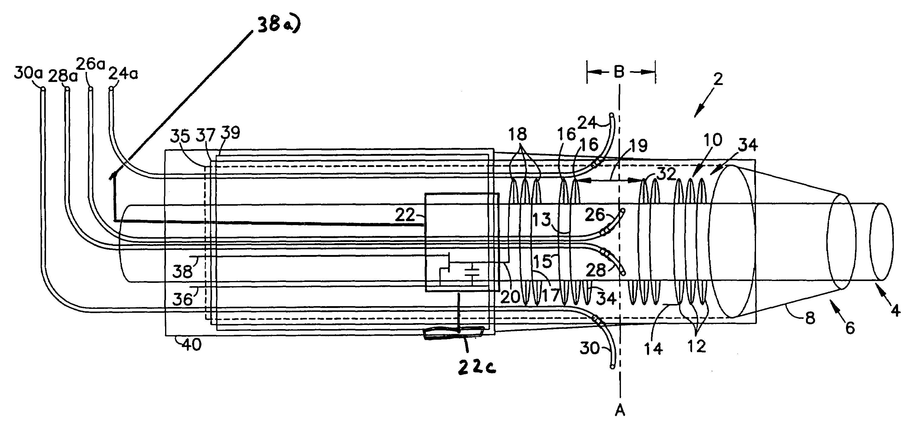
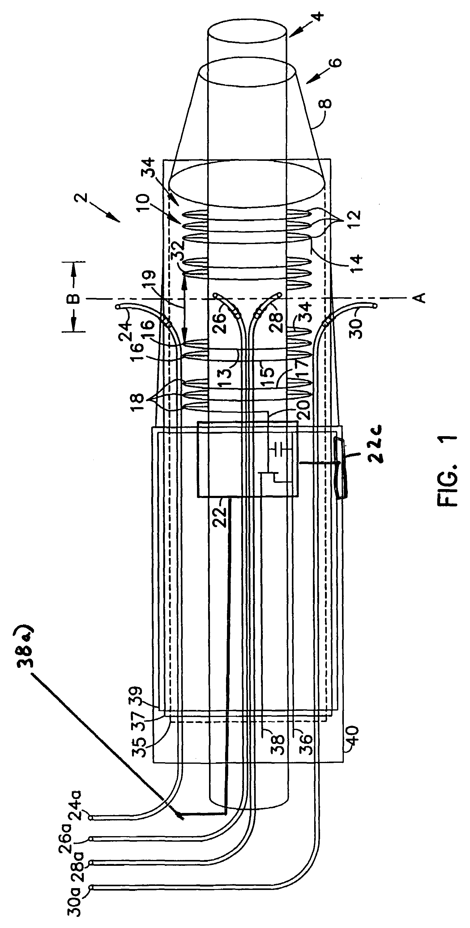
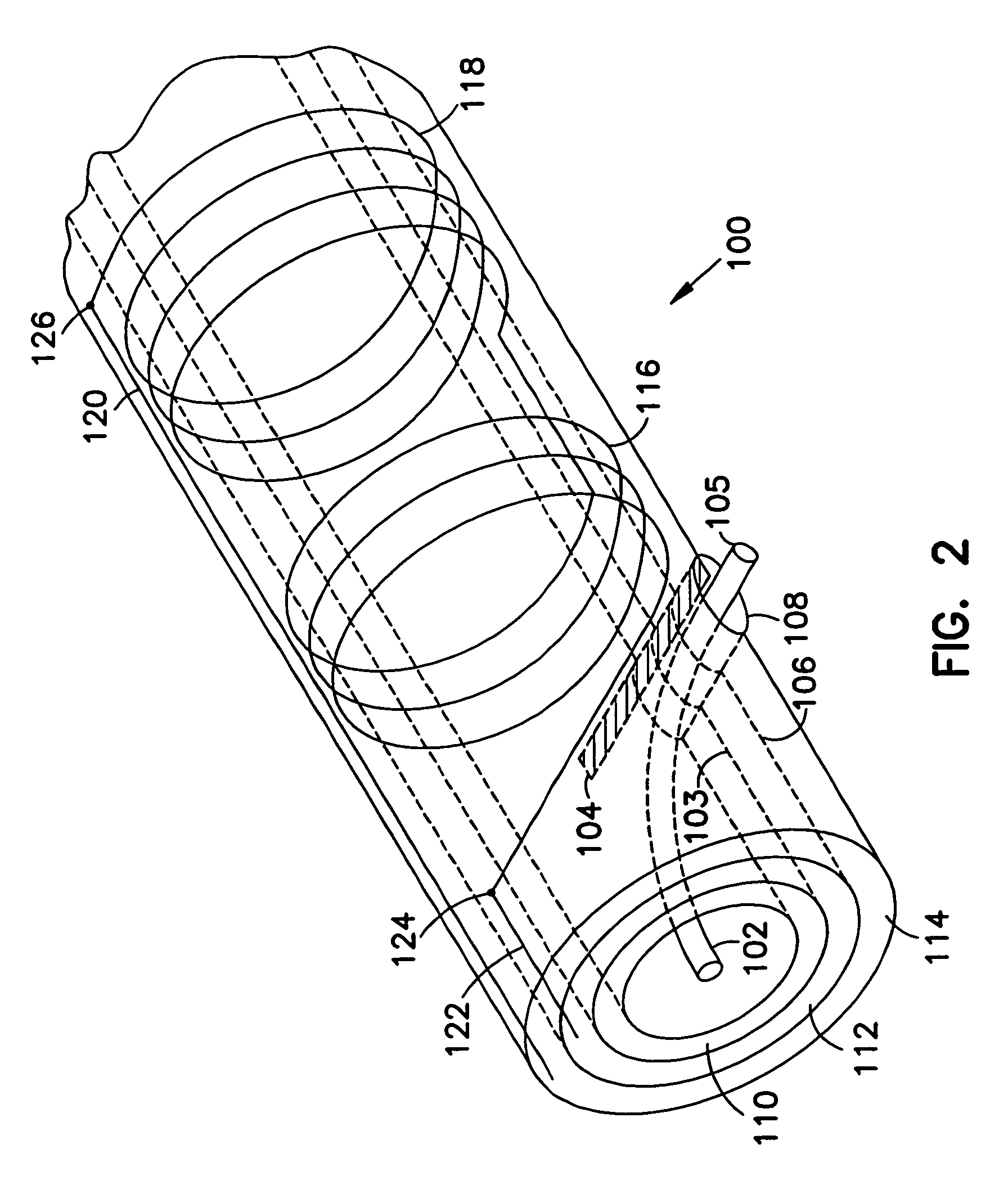
[0058]In the following detailed description of the preferred embodiments, references made to the accompanying drawings which form a part hereof, and in which is shown by way of illustration specific preferred embodiments in which the invention may be practiced. These embodiments are described in sufficient detail to enable those skilled in the art to practice the invention, and it is to be understood that other embodiments may be utilized and that structural, logical, physical, architectural, and electrical changes may be made without departing from the spirit and scope of the present invention. The following detailed description is, therefore, not to be taken in a limiting sense, and the scope of the present invention is defined only by the appended claims and their equivalents.

[0059]The practice of certain aspects of the present invention are applicable to all medical devices which might be used with magnetic resonance imaging viewing procedures occurring concurrently with the pri...


PUM


Abstract

A catheter is used for medical treatments within an organism. The catheter comprises at least one lumen. Within the at least one lumen are at least two microcatheters, with at least one of the at least two microcatheters being connected to a source of liquid material to be delivered to the organism and another of the at least two microcatheters being connected to a system capable of effecting a medical treatment other than delivery of the liquid.

Description

RELATED APPLICATIONS[0001]This application is a continuation-in-part of U.S. patent application Ser. No. 09 / 131,031, filed Aug. 7, 1998, now U.S. Pat. No. 6,272,370, and is also a continuation-in-part of U.S. patent application Ser. No. 08 / 857,043, filed May 15, 1997, now U.S. Pat. No. 6,026,316.BACKGROUND OF THE INVENTION[0002]1. Field of the Invention[0003]The present invention relates to a method of delivery of medical devices to patients, especially a method where (e.g., neurological) devices are delivered using nonlinear magnetic stereotaxis in conjunction with non-invasive MR imaging observation techniques such as magnetic resonance imaging, and most especially where drug delivery by said devices is accomplished under real time, non-invasive observation techniques such as magnetic resonance imaging which can indicate metabolic responses to the delivered drug and / or changes in soluble / dispersed concentrations of materials within liquids and / or tissue of a patient in real time o...

Claims


Application Information

Patent Timeline
IPC IPC(8): A61M5/178A61B5/05A61M29/00
CPCA61M25/0043G01R33/285A61M25/0127A61M25/0108
Inventor KUCHARCZYK, JOHNTRUWIT, CHARLES L.LIU, HAIYINGMOSELEY, MICHAEL E.
Owner STANDFORD UNIV
Learn More