

Electronic vehicle theft preventive device
a technology of electronic vehicle and anti-theft device, which is applied in the direction of anti-theft devices, programs, instruments, etc., can solve the problems of erronely actuation of the electronic steering wheel lock apparatus, and achieve the effect of high reliability
- Summary
- Abstract
- Description
- Claims
- Application Information
AI Technical Summary
Benefits of technology
Problems solved by technology
Method used
Image

Examples
first embodiment
(First Embodiment)
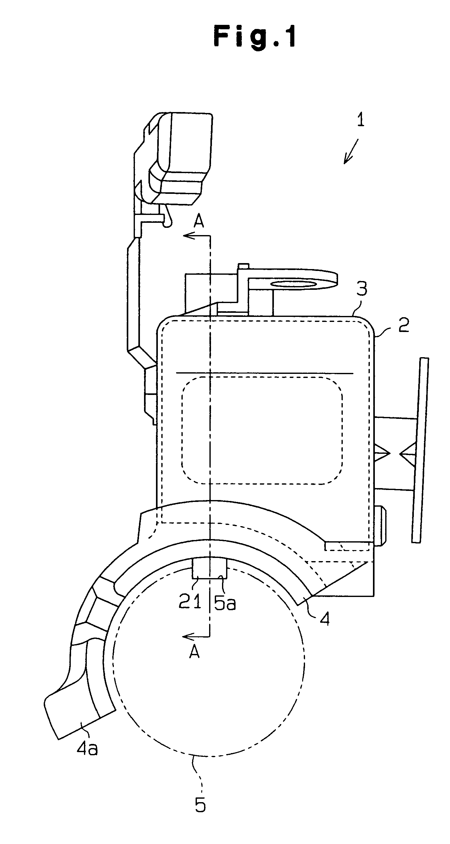
[0025]An electronic anti-theft apparatus according to a first embodiment of the present invention is described hereinafter with reference to FIGS. 1 through 3. The anti-theft apparatus locks a movable component 5 that moves when a vehicle is being driven. The movable component 5 includes, for example, a steering shaft 5, wheels, and a shift lever.
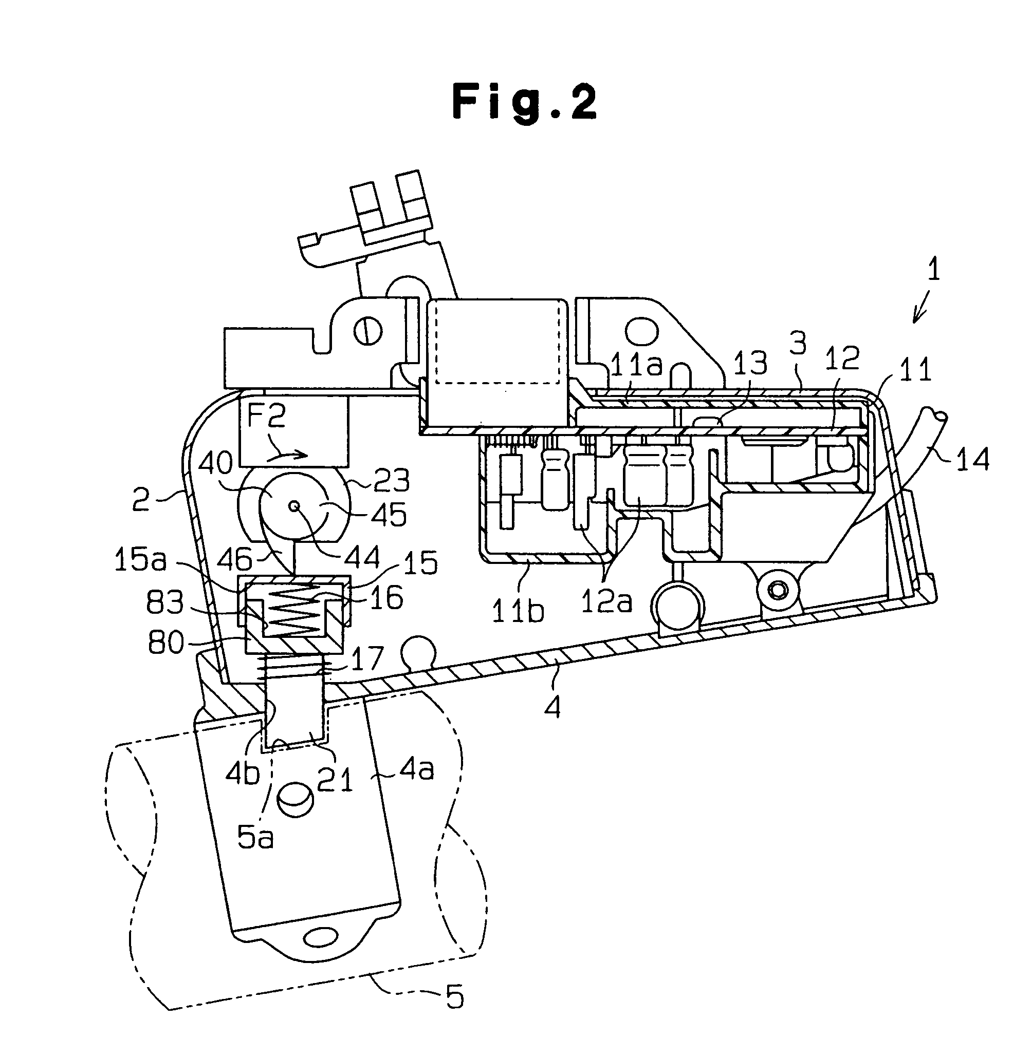
[0026]As shown in FIGS. 1 and 2, a steering wheel lock apparatus 1 is connected to a vehicle steering post (not shown in the drawings). A case body 2 of the steering wheel lock apparatus 1 is generally box-like. The case body 2 includes a cover 3 mounted on a lock body 4.
[0027]As shown in FIG. 2, a synthetic resin holding case 11 is provided on the interior side of the cover 3. The holding case 11 is formed by combining a first case 11a and a second case 11b. A printed circuit board 12 is accommodated in the holding case 11. The printed circuit board 12 is fixed to the second casing 11b by a screw 13. A plurality of electr...
second embodiment
(Second Embodiment)
[0053]A steering wheel lock apparatus 1 according to a second embodiment of the present invention is described hereinafter with reference to FIG. 4A. Each of the following embodiments is mainly described in terms of differences relative to the first embodiment.
[0054]As shown in FIG. 4A, the ignition power supply line 82 is divided into a first branch line 82a and a second branch line 82b at node 82c. Current flows through the first branch line 82a to power an electronic fuel injection control device and other electrical components.
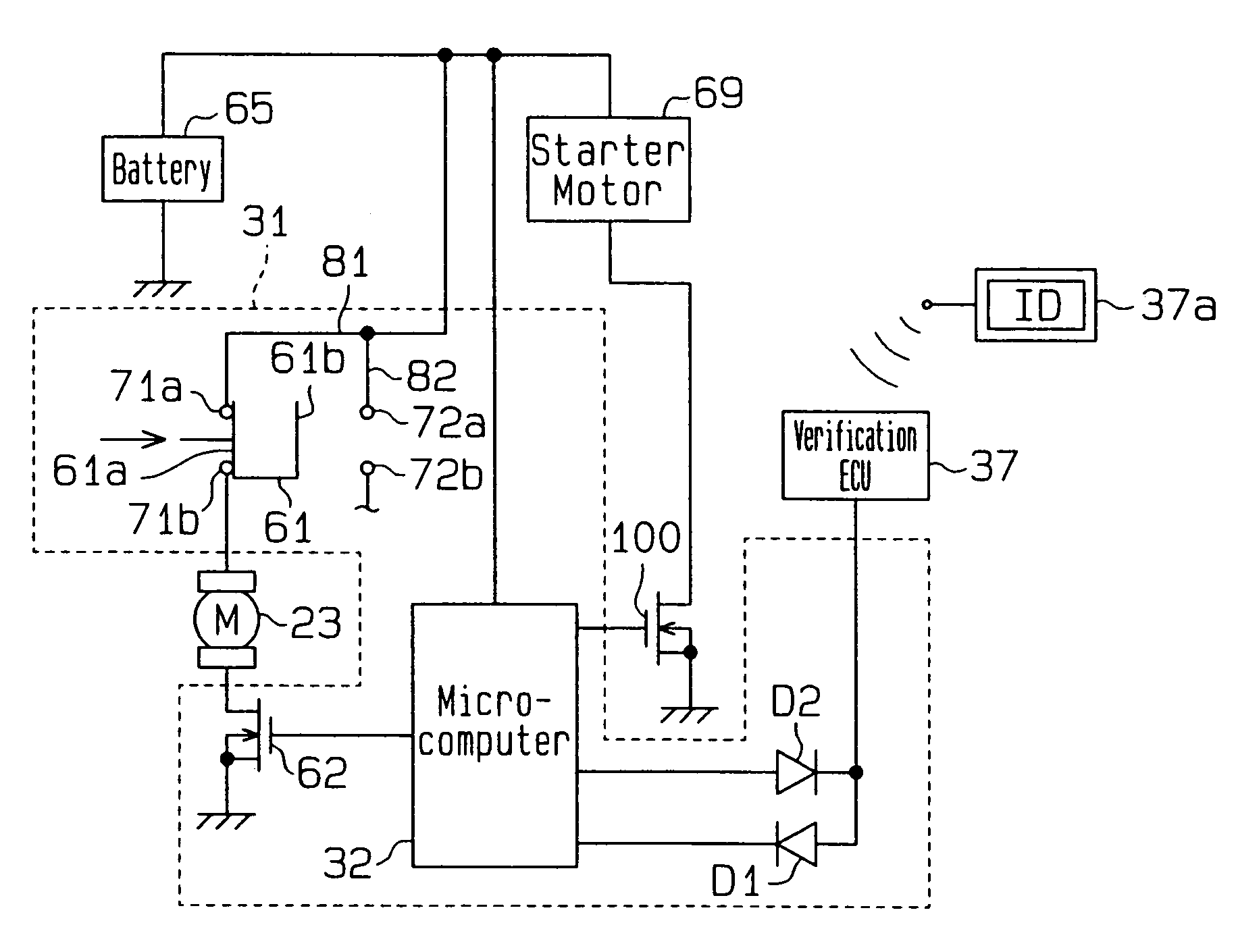
[0055]As further shown in FIG. 4A, in the second embodiment, a switching circuit including a relay 91 is used in place of the switch 61 of FIG. 3. The relay 91 has a contact 91a and a coil 93, which functions as an attraction element. The contact 91a is connected to the motor power supply line 81, and the coil 93 is connected to the second branch line 82b. The contact 91a is formed by a first contact pair 71a and 71b and a movable termin...
third embodiment
(Third Embodiment)
[0062]The steering wheel lock apparatus 1 according to a third embodiment of the present invention is described hereinafter with reference to FIGS. 5 and 6.
[0063]The point differing from the first embodiment is in that a lock position detection switch 38, resistor R, and a diode D3 are connected to the actuator ECU 31, as shown in FIG. 5.
[0064]As shown in FIG. 6, the lock position detection switch 38 is a normal-closed type mechanical switch arranged at the basal end of the lock pin 21 and is desirably a limit switch. The lock position detection switch 38 is closed when the lock pin 21 protrudes from the guide hole 4b of the lock body 4, as shown in FIG. 6A. The lock position detection switch 38 is opened when the lock pin 21 is accommodated within the lock body 4. That is, the lock position detection switch 38 is closed when the lock pin 21 engages the socket 5a of the steering shaft 5 and is opened when the engagement with the socket 5a is released.
[0065]As shown...
PUM
 Abstract
Description
Claims
Application Information