Manufacturing methods and systems for rapid production of hearing-aid shells

a manufacturing method and hearing aid technology, applied in image data processing, programme control, instruments, etc., can solve the problems of manual operation, large number of manual operations, and process restart, and achieve the effect of reducing the number of manual and time-consuming production steps and operations, high degree of quality assurance and reliability, and high degree of functionality

Active Publication Date: 2006-05-23
PHONAK
View PDF87 Cites 93 Cited by
  • Summary
  • Abstract
  • Description
  • Claims
  • Application Information

AI Technical Summary

Benefits of technology

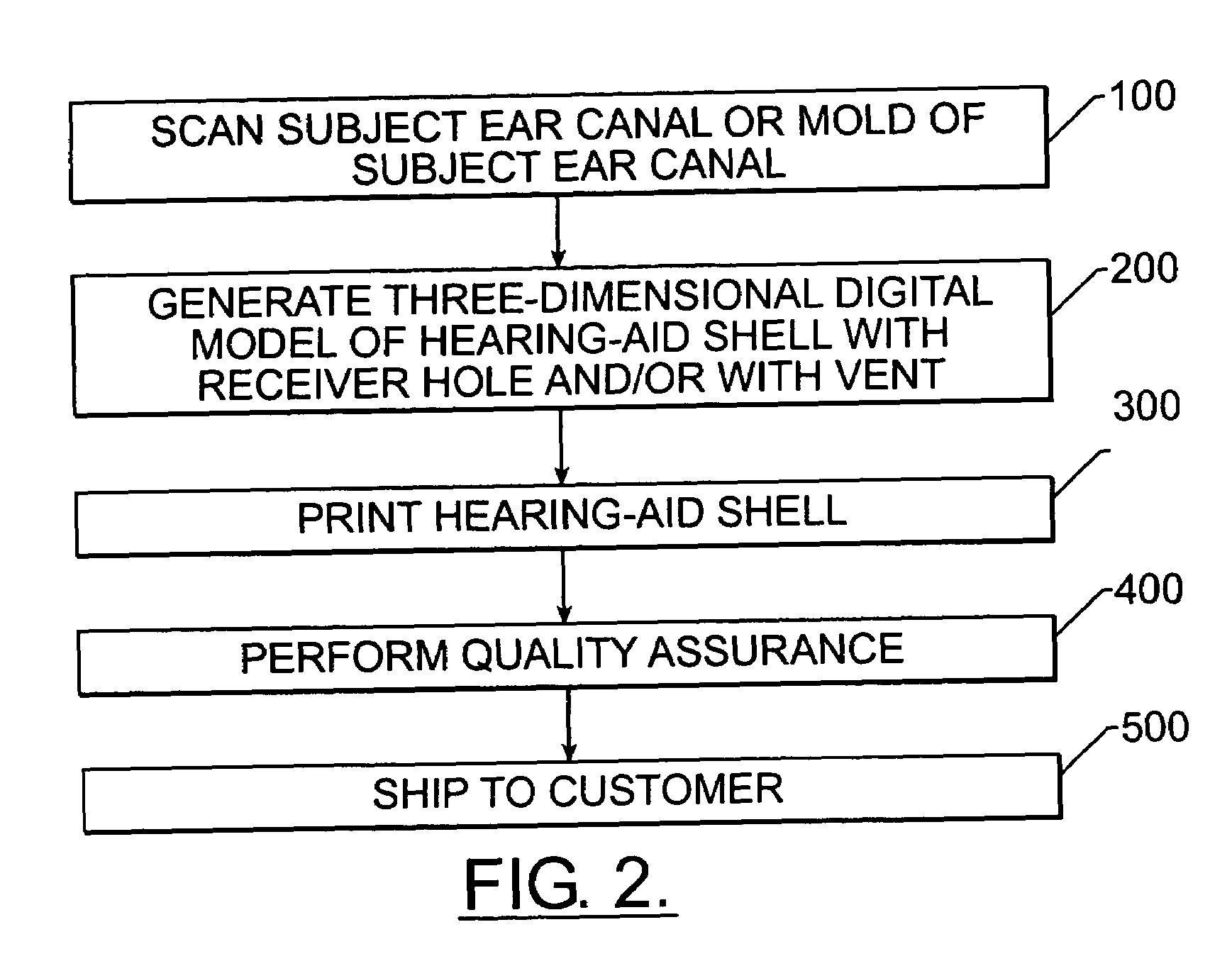
[0006]Methods, apparatus and computer program products of the present invention provide efficient techniques for designing and printing shells of hearing-aid devices with a high degree of quality assurance and reliability and with a reduced number of manual and time consuming production steps and operations. These techniques also prefe...

Problems solved by technology

Moreover, cosmetic considerations also frequently drive designers to smaller and smaller external dimensions while considerations of efficacy in hearing improvement typically constrain designers to certain minimal internal dimensions notwithstanding continued miniaturization of the electrical components.
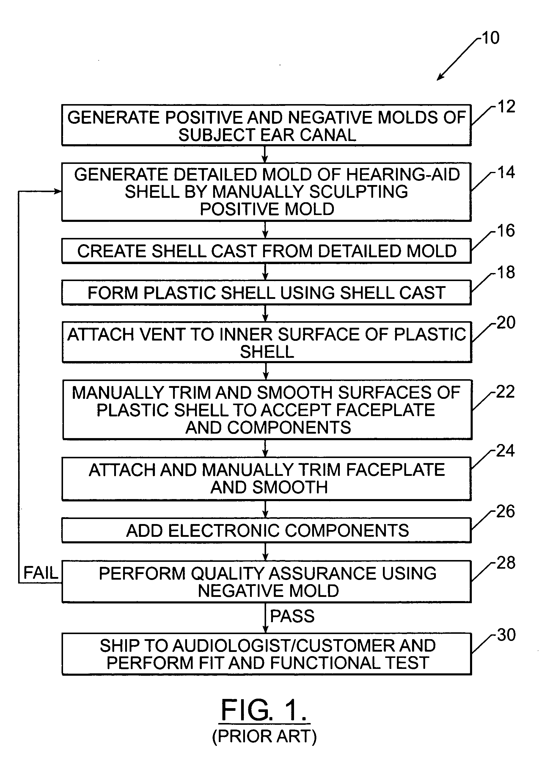
A failure of this test typically cause the manufacturing process to restart at the step of generating a detailed positive mold, Block 14.
A failure at this stage typically requires the repeat performance of the process flow 10 and the additional costs and time delay associated there...

Method used


Image

  • Manufacturing methods and systems for rapid production of hearing-aid shells
  • Manufacturing methods and systems for rapid production of hearing-aid shells
  • Manufacturing methods and systems for rapid production of hearing-aid shells

Examples


Embodiment Construction

[0036]The present invention now will be described more fully hereinafter with reference to the accompanying drawings, in which preferred embodiments of the invention are shown. This invention may, however, be embodied in many different forms and applied to other articles and should not be construed as limited to the embodiments set forth herein; rather, these embodiments are provided so that this disclosure will be thorough and complete, and will fully convey the scope of the invention to those skilled in the art. The operations of the present invention, as described more fully hereinbelow and in the accompanying figures, may be performed by an entirely hardware embodiment or, more preferably, an embodiment combining both software and hardware aspects and some degree of user input. Furthermore, aspects of the present invention may take the form of a computer program product on a computer-readable storage medium having computer-readable program code embodied in the medium. Any suitab...


PUM

PropertyMeasurementUnit
Thicknessaaaaaaaaaa
Sizeaaaaaaaaaa
Volumeaaaaaaaaaa

Abstract

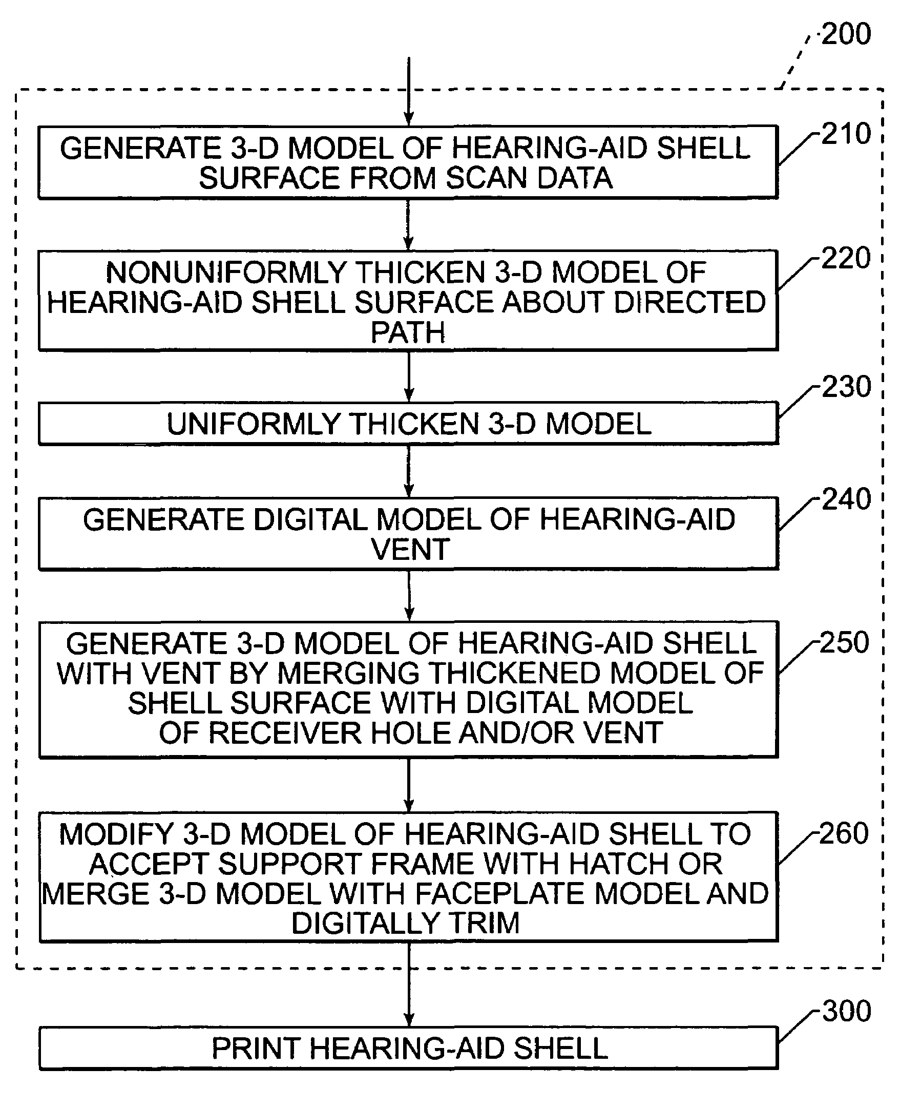
Methods, apparatus and computer program products provide efficient techniques for designing and printing shells of hearing-aid devices with a high degree of quality assurance and reliability and with a reduced number of manual and time consuming production steps and operations. These techniques also preferably provide hearing-aid shells having internal volumes that can approach a maximum allowable ratio of internal volume relative to external volume. These high internal volumes facilitate the inclusion of hearing-aid electrical components having higher degrees of functionality and/or the use of smaller and less conspicuous hearing-aid shells. A preferred method includes operations to generate a watertight digital model of a hearing-aid shell by thickening a three-dimensional digital model of a shell surface in a manner that eliminates self-intersections and results in a thickened model having an internal volume that is a high percentage of an external volume of the model. This thickening operation preferably includes nonuniformly thickening the digital model of a shell surface about a directed path that identifies a location of an undersurface hearing-aid vent. This directed path may be drawn on the shell surface by a technician (e.g., audiologist) or computer-aided design operator, for example. Operations are then preferably performed to generate a digital model of an undersurface hearing-aid vent in the thickened model of the shell surface, at a location proximate the directed path.

Description

FIELD OF THE INVENTION[0001]This invention relates to manufacturing methods and systems that utilize computer-aided-design (CAD) and computer-aided manufacturing (CAM) techniques and, more particularly, to manufacturing methods and systems for production of custom medical devices.BACKGROUND OF THE INVENTION[0002]Techniques for designing and manufacturing in-ear hearing-aid devices typically need to be highly customized in both internal dimensions to support personalized electrical components to remedy a individual's particular hearing loss need, and in external dimensions to fit comfortably and securely within an ear canal of the individual. Moreover, cosmetic considerations also frequently drive designers to smaller and smaller external dimensions while considerations of efficacy in hearing improvement typically constrain designers to certain minimal internal dimensions notwithstanding continued miniaturization of the electrical components.[0003]FIG. 1 illustrates a conventional pr...

Claims


Application Information

Patent Timeline
IPC IPC(8): G06F19/00B29C33/38B29C67/00G05B19/4099H04R25/00H04R31/00
CPCG05B19/4099H04R25/658B29C67/0051G05B2219/32189G05B2219/45172H04R2460/11H04R25/652H04R2225/77G05B2219/49008B33Y50/00B33Y80/00Y02A90/10B33Y50/02
Inventor FU, PINGNEKHAYEV, DMITRYEDELSBRUNNER, HERBERT
Owner PHONAK
Why Eureka
Try Eureka