Decoder an decoding method

a decoding method and softoutput technology, applied in the direction of coding, error correction/detection using convolutional codes, error correction/detection using turbo codes, etc., can solve the problem of difficult to accurately limited quantization range, and difficult to determine the log likelihood isub>t/sub>

Inactive Publication Date: 2006-05-23
SONY CORP
View PDF0 Cites 17 Cited by
  • Summary
  • Abstract
  • Description
  • Claims
  • Application Information

AI Technical Summary

Benefits of technology

[0066]In view of the above identified circumstances, it is therefore the object of the present invention to provide a decoder and a decoding method that can select an optimal dynamic range and an optimal quantization slot when the input needs to be made with a fixed number of bits.

Problems solved by technology

However, the above described BCJR algorithm requires computations to be made by directly holding probability values and the computations involve a large number of operations of multiplication, which by turn entails a problem of a large volume of computing operation.
However, when a decoder 203 is actually installed as hardware, it is difficult to determine the log likelihood Iγt by the arrangement of FIG. 6 because the quantization range is limited.
Therefore, the decoder 203 cannot be provided with a dynamic range that is wide enough for satisfactorily expressing information on the received value and hence it is difficult to accurately determine the log likelihood Iγt.
Thus, if a priori probability information APP becomes very fine and goes beyond the allowable range of quantization, it will be no longer possible to express a priori probability information APP.

Method used


Image

  • Decoder an decoding method
  • Decoder an decoding method
  • Decoder an decoding method

Examples


Embodiment Construction

[0112]Now, the present invention will be described in greater detail by referring to the accompanying drawings that illustrate a preferred embodiment of the invention.

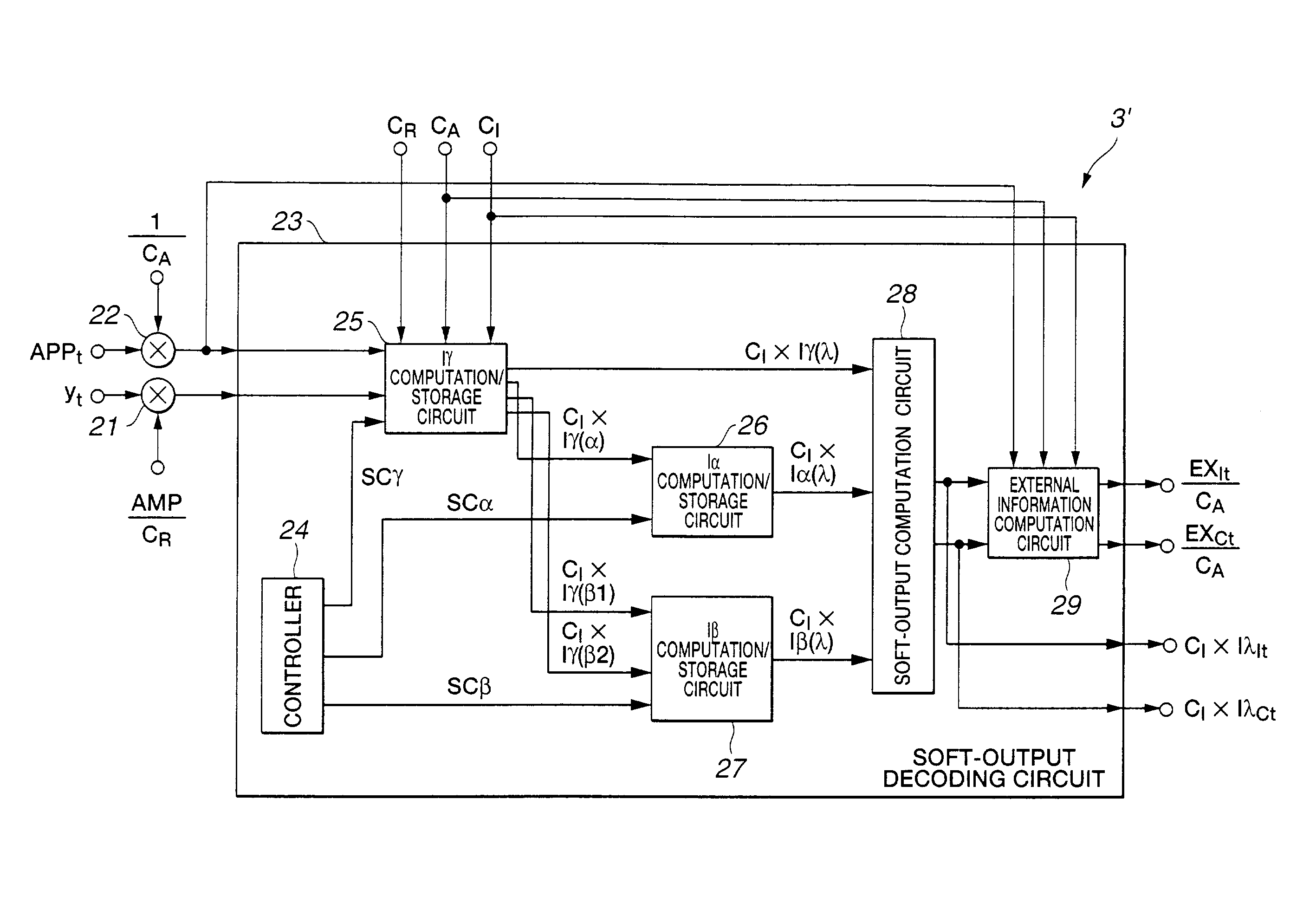
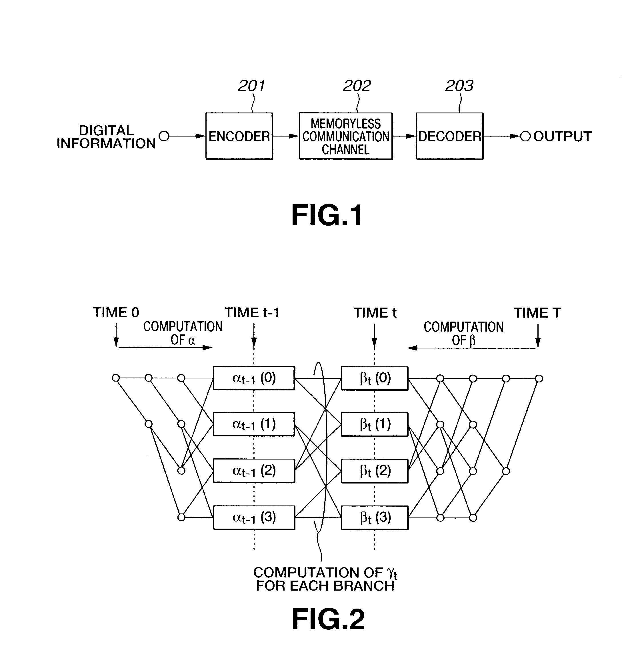
[0113]Referring firstly to FIG. 10, this embodiment is applied to a data transmission / reception system, in which having encoder 1 of a transmitter (not shown) encodes digital information and transmits it to a receiver (not shown) by way of a memoryless communication path 2 having noise so that the transmitted code is decoded by decoder 3 of the receiver.

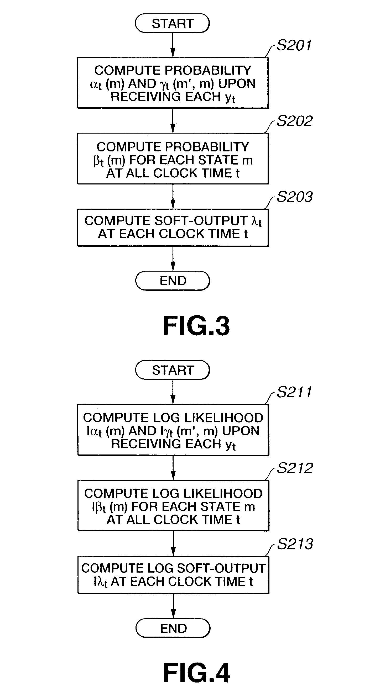
[0114]Of the data transmission / reception system, the decoding operation of the decoder 3 for decoding the code encoded by the encoder 1 is a maximum a posteriori probability (to be referred to as MAP hereinafter) decoding operation that is conducted on the basis of the Max-Log-MAP algorithm or the Log-MAP algorithm (to be referred to as Max-Log-BCJR algorithm or Log-BCJR algorithm, whichever appropriate, hereinafter) as described in Robertson, Villebrun and Hoeher, “A c...


PUM


Abstract

A decoder that receives, as input, probability information AMP/CR×yt. This probability information is obtained by dividing a channel value obtained by multiplication of received value yt and a predetermined coefficient AMP by the first additive coefficient CR for regulating the amplitude of the received value yt and the probability information 1/CA×APPt obtained by multiplying the a priori probability information APPt by the reciprocal of the second additive coefficient CA for regulating the amplitude of the a priori probability information APPt to a soft-output decoding circuit. The soft-output decoding circuit, which may be a large scale intergrated circuit, generates log soft-output CI×Iλt and/or external information 1/CA×EXt using additive coefficients for regulating the amplitude of arithmetic operations in the inside of the soft-output decoding circuit.

Description

TECHNICAL FIELD[0001]This invention relates to a decoder and a decoding method for decoding a soft-output.BACKGROUND ART[0002]Research efforts have been made in recent years for reducing symbol error rates by using soft-outputs for decoded outputs of inner codes of concatenated codes and also for outputs of iterative decoding operations using an iterative decoding method. Studies of decoding methods for minimizing symbol error rates are being made extensively. For example, Bahl, Cock, Jelinek and Raviv, “Optimal decoding of linear codes for minimizing symbol error rate” IEEE Trans. Inf. Theory, vol. IT-20, pp. 284–287, March 1974, describes BCJR algorithm as a method for minimizing the symbol error rate when decoding a predetermined code such as a convolutional code. The BCJR algorithm is adapted to output the likelihood of each symbol instead of outputting each symbol as a result of a decoding operation. Such an output is referred to as soft-output. Now, the BCJR algorithm will be ...

Claims


Application Information

Patent Timeline
Patent Type & Authority Patents(United States)
IPC IPC(8): H03M13/03H03M13/00G06F11/10H03M13/23H03M13/27H03M13/29H03M13/41H03M13/45
CPCH03M13/27H03M13/29H03M13/2957H03M13/658H03M13/3905H03M13/6337H03M13/6577H03M13/258H03M13/2972
Inventor MIYAUCHI, TOSHIYUKIHATTORI, MASAYUKIYAMAMOTO, KOUHEIYOKOKAWA, TAKASHI
Owner SONY CORP
Why Eureka
Try Eureka