Ultrasonic probe and ultrasonic diagnostic equipment

a technology of ultrasonic probes and diagnostic equipment, applied in diagnostics, medical science, surgery, etc., can solve the problems of difficult to render adequate characteristics of ultrasonic transducers, problems with ultrasonic probes, and conventional acoustic media in ultrasonic probes and ultrasonic scopes, so as to reduce the capacity of an acoustic medium

Inactive Publication Date: 2006-05-30
OLYMPUS CORP
View PDF2 Cites 18 Cited by
  • Summary
  • Abstract
  • Description
  • Claims
  • Application Information

AI Technical Summary

Benefits of technology

[0009]It is an object of the present invention to provide an ultrasonic probe, in which ultrasonic attenuation at high frequencies is small and decrease of the capacity of an acoustic medium due to volatilization can be reduced, and ultrasonic diagnostic equipment using this ultrasonic probe.
[0012]To put it briefly, the ultrasonic probe of the present invention is the ultrasonic probe for producing an ultrasonic image by mechanically driving the ultrasonic transducer, and by using the hydrocarbon-based oil having a kinematic viscosity of 20 mm2 / s or less as the acoustic medium allowed to fill in between the ultrasonic transducer and the acoustic window which is in contact with a living body and which transmits an ultrasonic wave, the characteristic of ultrasonic attenuation at high frequencies can be reduced, an ultrasonic image at a significant ultimate depth can be produced and, in addition, decrease of the capacity of the acoustic medium due to volatilization can be reduced.

Problems solved by technology

However, conventional acoustic media in ultrasonic probes and ultrasonic scopes-which produced ultrasonic images by mechanically rotating or shaking ultrasonic transducers had problems as described below.
However, regarding ultrasonic transducers of high frequencies of 10 MHz or more, since ultrasonic attenuation in the liquid paraffin is large, it is difficult to render adequate characteristics.

Method used


Image

  • Ultrasonic probe and ultrasonic diagnostic equipment
  • Ultrasonic probe and ultrasonic diagnostic equipment
  • Ultrasonic probe and ultrasonic diagnostic equipment

Examples


Embodiment Construction

[0017]The present embodiments will be described with reference to the drawings.

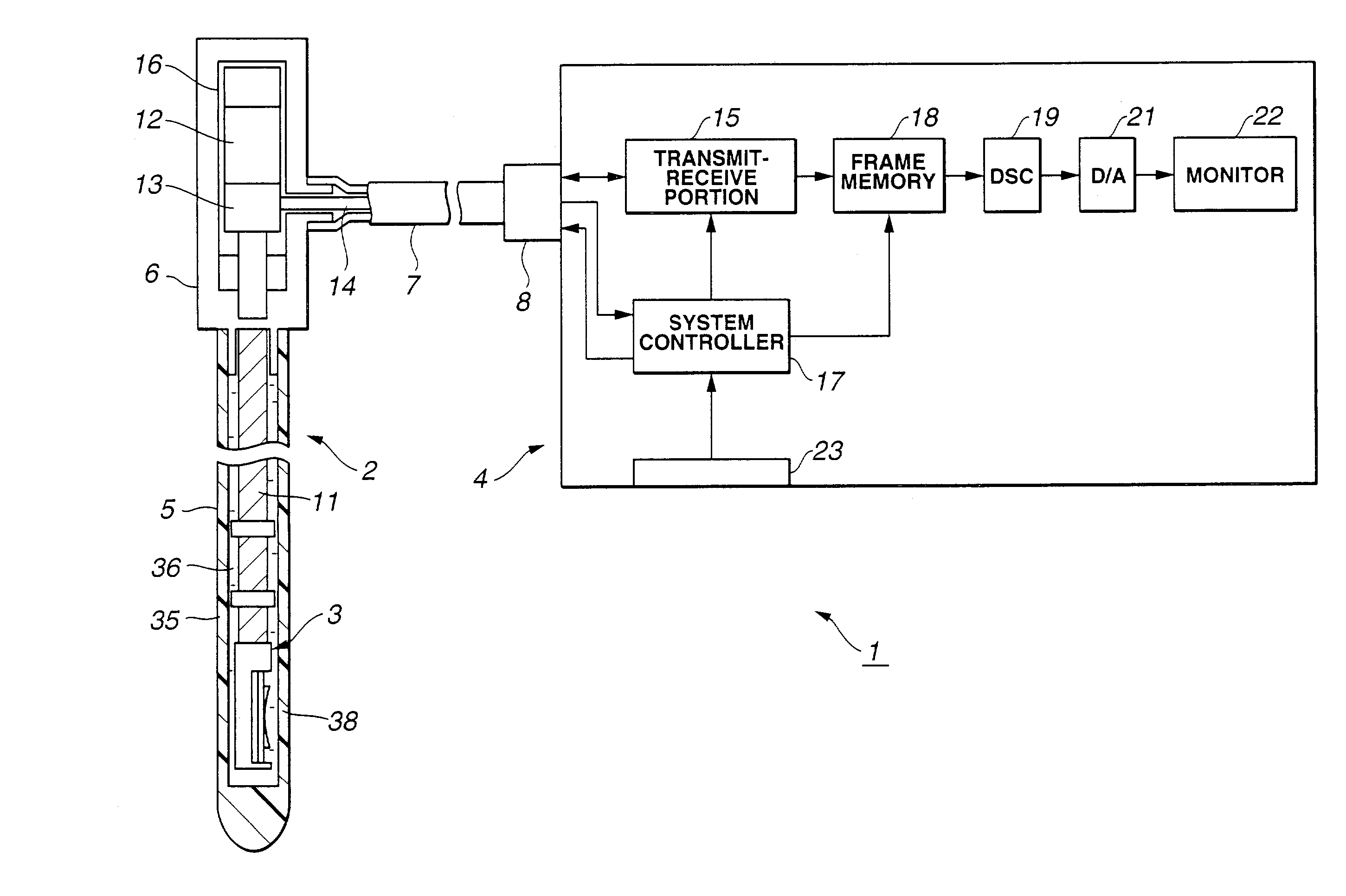
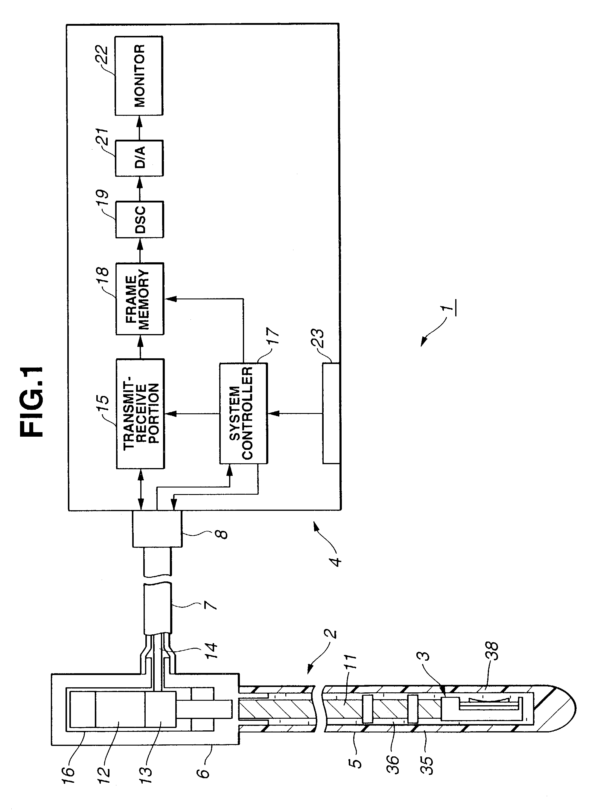
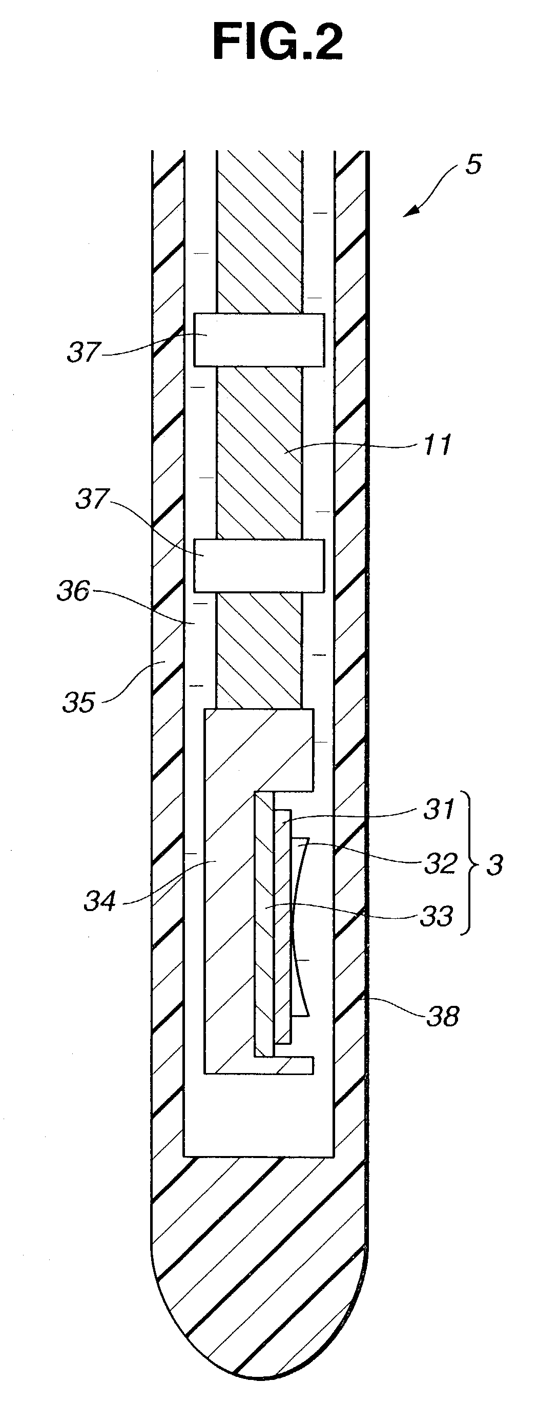
[0018]FIGS. 1 and 2 relate to an embodiment of the present invention. FIG. 1 shows the total configuration of ultrasonic diagnostic equipment provided with the embodiment, and FIG. 2 shows the structure of the distal end portion of an ultrasonic probe.

[0019]As shown in FIG. 1, the ultrasonic diagnostic equipment 1 is composed of an ultrasonic probe 2 which is inserted into a body cavity, etc., so as to perform transmission and reception of the ultrasonic wave with respect to an examined body and an ultrasonic observation apparatus 4 which is connected to this ultrasonic probe 2 and which displays an ultrasonic image by performing signal processing with respect to an ultrasonic transducer 3 built in the ultrasonic probe 2 and the like.

[0020]The ultrasonic probe 2 includes a slender and flexible insertion portion 5 to be inserted into a body cavity, etc., a holding portion 6 arranged at the rear end of this...


PUM


Abstract

A flexible shaft is inserted through a sheath constituting an insertion portion of an ultrasonic probe connected to an ultrasonic observation apparatus, an ultrasonic transducer driven to rotate, etc., is attached at the distal end portion thereof, and an ultrasonic wave can be transmitted and received through an acoustic window arranged around thereof. By using hydrocarbon-based oil having a kinematic viscosity of 20 mm2 / s as an acoustic medium for filling the surrounding of the ultrasonic transducer in the acoustic window, ultrasonic attenuation at high frequencies can be reduced, decrease of the capacity of the acoustic medium due to volatilization can be reduced, and decrease of the capacity of the acoustic medium due to volatilization is reduced.

Description

BACKGROUND OF THE INVENTION[0001]1, Field of the invention[0002]The present invention relates to an ultrasonic probe and ultrasonic diagnostic equipment provided with an ultrasonic transducer used for ultrasonic observation.[0003]2, Related Art Statement[0004]In an ultrasonic probe and an ultrasonic endoscope which produce an ultrasonic image by mechanically rotating or shaking an ultrasonic transducer, an acoustic medium which transmits an ultrasonic wave is allowed to fill in between the ultrasonic transducer and a sheath storing it or a cap.[0005]Conventionally, liquid paraffin having low toxicity to a living body, water, carboxymethyl cellulose (CMC) aqueous solutions, and the like have been used as the acoustic medium.[0006]However, conventional acoustic media in ultrasonic probes and ultrasonic scopes-which produced ultrasonic images by mechanically rotating or shaking ultrasonic transducers had problems as described below.[0007]When water or an aqueous solution of carboxymeth...

Claims


Application Information

Patent Timeline
Patent Type & Authority Patents(United States)
IPC IPC(8): A61B8/12A61B8/00G10K11/02
CPCA61B8/12A61B8/4281A61B8/445G10K11/02A61B8/4461
Inventor FUKUDA, HIROSHIOMURA, MASAYOSHI
Owner OLYMPUS CORP
Why Eureka
Try Eureka