Eureka AIR delivers breakthrough ideas for toughest innovation challenges, trusted by R&D personnel around the world.

Inflatable heating device for in-situ repair of conduit and method for repairing conduit

a heating device and inflatable technology, applied in the field of inflatable heating devices and the field of forming devices, can solve the problems of losing electrical continuity and heating capability, inferior curing of ambient materials, and limiting the flexibility of heaters through the use of wires such as wires, so as to reduce cycle time in production, inflatable heating, and prolong the life cycle

Inactive Publication Date: 2006-05-30
EMS USA HLDG I +1
View PDF74 Cites 64 Cited by
  • Summary
  • Abstract
  • Description
  • Claims
  • Application Information

AI Technical Summary

Benefits of technology

[0010]An object of one embodiment of the invention is to overcome the problems associated with flexible, inflatable heaters which incorporate metallic heating elements, and to provide a robust, inflatable heating device with an extended life cycle. Another object is to provide an inflatable heating device and process for manufacturing such devices which can reduce the cycle time in production and reduce the capital equipment costs associated with the production.

Problems solved by technology

Ambient curing is inferior, however, because ambient conditions may vary widely and disrupt the curing cycle.
While these wires are an efficient heating element, the flexibility of the heater is limited by the use of such wires.
With the repeated inflating and deflating that would be experienced with repeated use, it is expected that the redundant load paths associated with the flexing will cause the copper wires to fail, thus losing electrical continuity and heating capability.
This severally limits the life cycle of a flexible heater manufactured with metallic wires.
Copper wires disposed in a flexible composition also exhibit very poor adhesion to the surrounding polymer (usually silicon) making uniform and consistent positioning of the wires within the polymer matrix, throughout the expected life cycle of the heater, difficult if not impossible.
This can result in the resistance wires being redistributed within the heater in undesired arrangements.
While various primers can be employed to increase the bond strength between the polymer matrix and the wires, such primers can further degrade the flexible strength of the wire and limit its malleability, causing premature failure.
The relatively high mass of copper or other electrically conductive metal, also results in a lag in response time when used as a heating element, thus requiring constant monitoring and adjustment of the power supply.
In these resin types, certain chemicals are present that have a detrimental effect on silicone products.
Specifically, silicones, when exposed to certain chemicals such as styrene, which is present in many resin systems, and heat, will revert after a limited number of uses to into a weak form no longer suitable as an inflation device.
However, the ovens required are expensive and generally inefficient, as they must heat a large volume of air as well as the mandrel or forming surface, and the uncured strips.
Considerable energy is lost to the atmosphere and cycle times are lengthy in such a procedure.
This translates into excessively high manufacturing costs.

Method used


Image

  • Inflatable heating device for in-situ repair of conduit and method for repairing conduit
  • Inflatable heating device for in-situ repair of conduit and method for repairing conduit
  • Inflatable heating device for in-situ repair of conduit and method for repairing conduit

Examples


Embodiment Construction

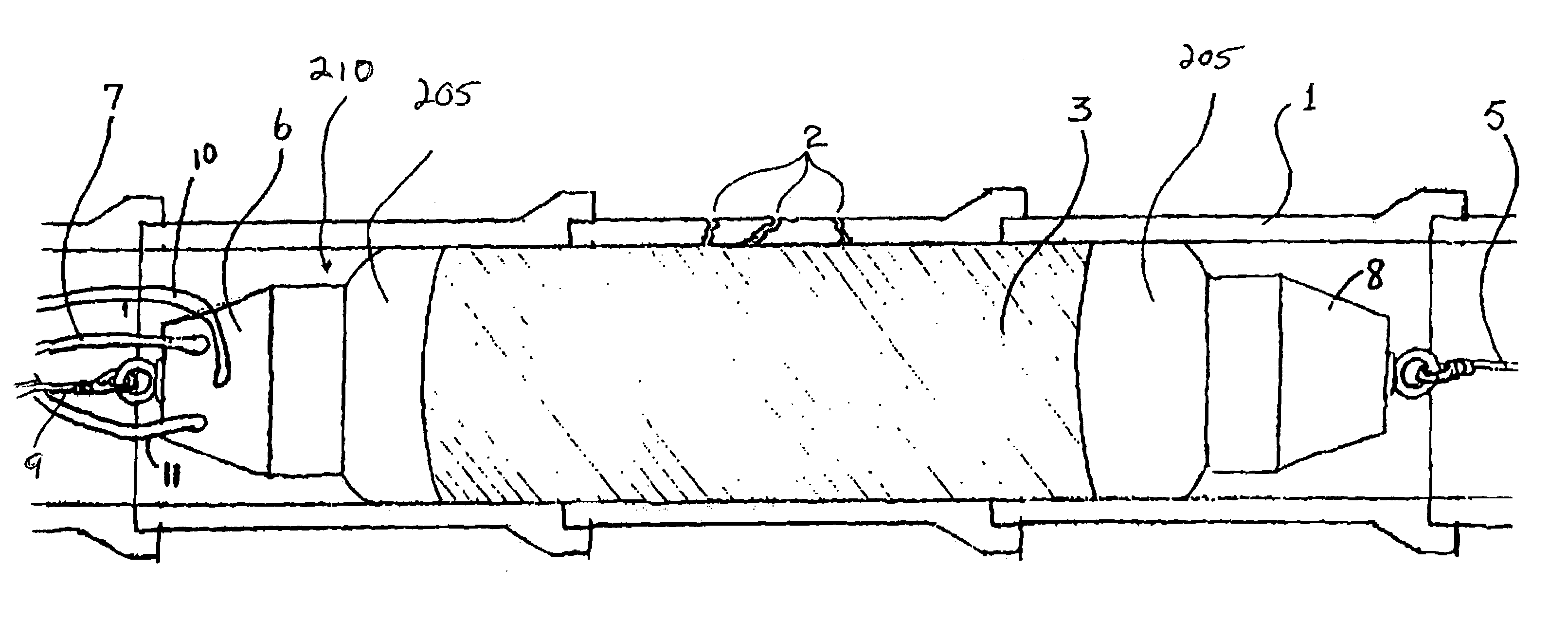
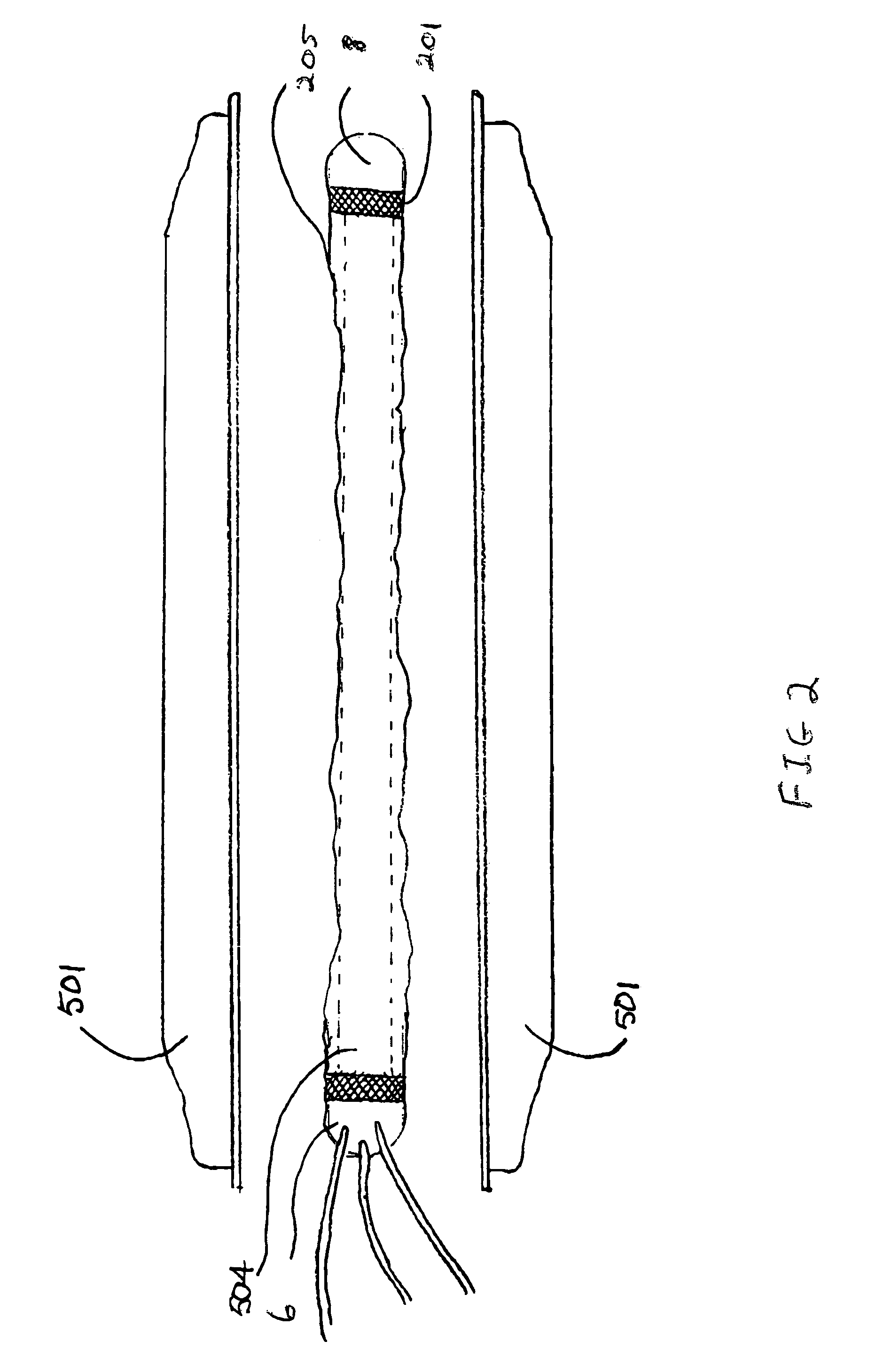
[0028]While this invention is susceptible of embodiments in many different forms, there is shown in the drawings and will herein be described in detail preferred embodiments of the invention with the understanding that the present disclosure is to be considered as an exemplification of the principles of the invention and is not intended to limit the broad aspect of the invention to the embodiments illustrated.

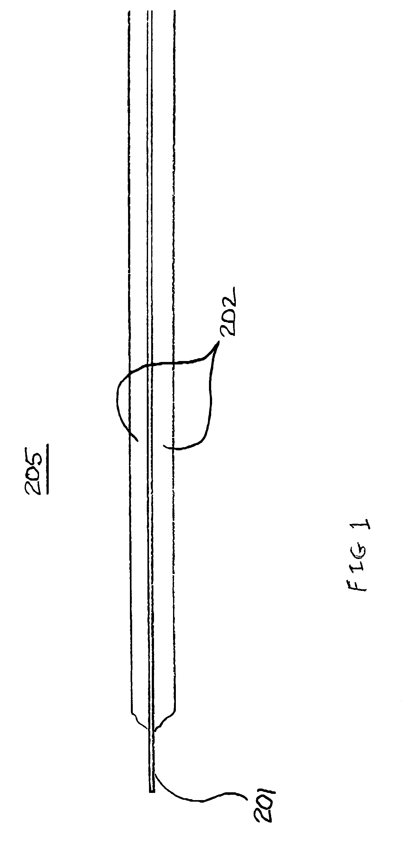
[0029]FIG. 1 cross-sectionally illustrates one embodiment of the composite 205 in accordance with the present invention. The composite 205 is inflatable or elastomeric, seamless, reinforced with structural braids 201, and for most applications generally cylindrical. The composite 205 is a single layer formed from one or more initially discrete layers that are consolidated by means of a thermoset resin 202. The resin 202 is preferably a silicone matrix such as methylvinylpolysiloxane, which will remain flexible after its application and cure. The core of the composite 205 contai...


PUM

PropertyMeasurementUnit
braid angleaaaaaaaaaa
angleaaaaaaaaaa
angleaaaaaaaaaa

Abstract

The apparatus of the present invention is generally characterized by a heating / inflation module having pressurizable interior and an attached heat curable pre-preg. In particular, an elastomeric, seamless composite is provided that includes a heating element disposed within a thermoset resin matrix. The composite adapted to maintain a consistent temperature profile and an internal air pressure. A first end piece is attached to a first end of the composite and has an air port for communication with a compressed air source, a vacuum port for communication with a vacuum supply source and at least one electrical cable port for communication with a power supply source. A second end piece attached to a second end of the composite. The apparatus further includes a pre-preg removably attached to an outer surface of the composite. The pre-preg includes a structural fiber matrix supporting a heat curable resin. The composite is constructed by applying a liquid silicone matrix to at least one layer of braided or wound and / or tape fibers, wherein a portion of the fibers are electrically conductive. The layer of braided fibers is introduced into a mold, and a removable, expandable inner bladder is then loaded into the mold. The inner bladder is inflated to conform the layer of braided fibers to an interior surface of the mold. An electric current is caused to flow to the conductive fibers to cure the silicone matrix into a stable, elastomeric state. The composite is removed from the mold. A method for repairing a damaged section of a conduit is also disclosed.

Description

RELATED U.S. PATENT APPLICATION[0001]This is a continuation-in-part of application Ser. No. 08 / 882,769, filed Jun. 26, 1997 now abandoned, which is a continuation-in-part of application Ser. No. 08 / 431,302 filed Apr. 28, 1995 now abandoned.TECHNICAL FIELD[0002]The present invention generally relates to an inflatable heating device and method of forming the device. More particularly, the invention relates to an inflatable heating device which can be inflated by a pressurized fluid and heated via an electrically conductive, non-ferrous matrix within the device's composition. The device can be used to provide compaction and heat sufficient to influence a physical reaction in a material in contact with the device's exterior, such as heating, compressing and curing a hardenable resin used in the in-situ repair of damaged conduits such as underground sewer pipes, and other structures having tubular or other three dimensional curvature.BACKGROUND OF THE INVENTION[0003]Use of composite mate...

Claims


Application Information

Patent Timeline
Patent Type & Authority Patents(United States)
IPC IPC(8): B29C63/28B29C73/32
CPCB29C35/0272B29C63/28F16L55/1645F16L55/163B29C70/342
Inventor BLACKMORE, RICHARD D.LEPOLA, WILLIAM M.
Owner EMS USA HLDG I
Why Eureka
Eureka Blog
Learn More