Magnetron cathode and magnetron sputtering apparatus comprising the same

a sputtering apparatus and magnetron technology, applied in the direction of electrolysis components, vacuum evaporation coatings, coatings, etc., can solve the problems of difficult to efficiently control the momentum of charged particles, difficult to satisfy such demands using a sputtering apparatus comprising a conventional magnetron cathode, and conventional magnetron cathode exhibits non-uniform magnetic field distribution, etc., to achieve uniform magnetic field distribution

Inactive Publication Date: 2006-05-30
SAMSUNG ELECTRONICS CO LTD
View PDF8 Cites 3 Cited by
  • Summary
  • Abstract
  • Description
  • Claims
  • Application Information

AI Technical Summary

Benefits of technology

[0034]The present invention provides a magnet structure of the three or mo

Problems solved by technology

However, it is known that it is difficult to efficiently control the momentum of charged particles, determining the sputtering efficiency in magnetron sputtering.
In addition, although demands for highly integrated devices, narrow line width, and large process wafers increase continuously, it is difficult to satisfy such demands using a sputtering apparatus comprising a conventional magnetron cathode.
However, a conventional magnetron cathode exhibits non-uniform magnetic field distribution, as shown in FIG. 2. FIG. 2 shows the magnetic field line distribution of a convent

Method used


Image

  • Magnetron cathode and magnetron sputtering apparatus comprising the same
  • Magnetron cathode and magnetron sputtering apparatus comprising the same
  • Magnetron cathode and magnetron sputtering apparatus comprising the same

Examples


Embodiment Construction

[0049]Korean Patent Application No. 2003-2731, filed on Jan. 15, 2003, and entitled: “Magnetron Cathode and Magnetron Sputtering Apparatus Comprising the Same,” is incorporated by reference herein in its entirety.

[0050]Hereinafter, a magnetron cathode and a magnetron sputtering apparatus comprising the same according to the present invention will be described in detail with reference to the accompanying drawings.

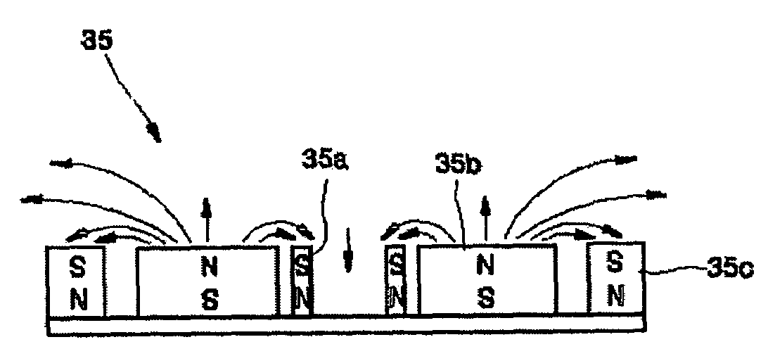
[0051]FIG. 5 is a schematic sectional view of a magnetron cathode according to the present invention.

[0052]Referring to FIG. 5, a magnetron cathode according to the present invention comprises three or more magnet units, each of which comprises a single magnet or a plurality of magnets having the same poles facing toward a target. Adjacent magnet units have opposite poles facing toward the target. One magnet unit is disposed around the outer circumference of another magnet unit. For example, as shown in FIG. 5, a first magnet unit 35a is disposed at the innermost area in suc...


PUM

PropertyMeasurementUnit
Polarityaaaaaaaaaa
Shapeaaaaaaaaaa
Widthaaaaaaaaaa

Abstract

A magnetron cathode and a sputtering apparatus including the same are provided. The magnetron cathode includes three or more magnet units, each of which comprises a single magnet or a plurality of magnets having the same poles facing toward the same direction, wherein one magnet unit is disposed around the outer circumference of another magnet unit and adjacent magnet units have opposite poles facing toward the same direction. Uniform magnetic field distribution is obtained. Therefore, the erosion profile of a target is wide and uniform.

Description

BACKGROUND OF THE INVENTION[0001]1. Field of the Invention[0002]The present invention relates to a magnetron sputtering apparatus, and more particularly, to a magnetron sputtering apparatus with improvements in deposition rate and film uniformity.[0003]2. Description of the Related Art[0004]Generally, physical vapor deposition (PVD) and chemical vapor deposition (CVD) are widely used for the deposition of films with a small thickness. The CVD is a process that forms thin films with desired physical properties using chemical reaction. The PVD is a process that forms thin films by imparting a momentum to target materials in order for the target materials to travel toward a substrate.[0005]The PVD can be largely classified into magnetron sputtering and evaporation. The evaporation is a method that heats a solid or a liquid to be decomposed into molecules or atoms and then solidifies them on a surface of a substrate. The evaporation has been widely used because an apparatus therefor has...

Claims


Application Information

Patent Timeline
IPC IPC(8): C23C14/00C23C14/35H01J37/317H01J37/34H01L21/285H01L21/31
CPCH01J37/3408C23C14/35H01J37/317
Inventor NAVALA, SERGIY YAKOVLEVICHTOLMACHEV, YURI NIKOLAEVICHMA, DONG-JOONKIM, TAE-WAN
Owner SAMSUNG ELECTRONICS CO LTD
Why Eureka
Try Eureka